Any G (board pic in Post #2511).
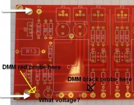
You are measuring voltage with respect to ground. It will be the DC voltage before the capacitor C3, so you can have the Red probe of the meter before or after R12 as long as the Black probe is in G.
You are measuring voltage with respect to ground. It will be the DC voltage before the capacitor C3, so you can have the Red probe of the meter before or after R12 as long as the Black probe is in G.
To check for DC offset? The capacitor is supposed to null out DC offset so you would want to check before the cap which will be one side of r12, you can follow the trace. For ground, you can reference the side of r2 that is facing the g solder pad or you can connect to the ground lead itself if you're probe will get around it.
I left r2 a little high so that way I would have a nice place to connect to
Keep a close eye on the multimeter connected to the source resistors. You want to see zero on those when you first click it on if you have the trimmer pots set the right way. If it starts rapidly going up, you need to turn the trimmer potentiometers the other way.


The DC offset is extremely touchy. If you so much as even breathe and one of the mosfets, it'll throw it off.
If you have it in a case, close the lid and let it sit for 10 minutes or so after you adjust. Also an AC vent turning on, a ceiling fan etc can throw it off.
If you have it in a case, close the lid and let it sit for 10 minutes or so after you adjust. Also an AC vent turning on, a ceiling fan etc can throw it off.
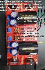
Black probe at Gnd, Red probe at V+ should read +24V.
Black probe at Gnd, Red probe at V- should read -24V.
Voltages are relative to Gnd.
Black probe at Gnd, Red probe at V- should read -24V.
Voltages are relative to Gnd.
Measuring at those two points, that sounds about right. You're black probe is supposed to be on ground. Then you would take your red probe and touch the Plus, should give you plus 24 volts, red lead to the negative should give you negative 24 volts.

Right, TO GROUND!Black probe at Gnd, Red probe at V+ should read +24V.
Black probe at Gnd, Red probe at V- should read -24V.
Voltages are relative to Gnd.
I now get 21.95 DCV +/-.
I have some experience with biasing and things are not going well. Mostly weird.
As I increase bias to 0.035 ish offset starts to oscillate and I can't get it to dial down.
Then the values on bias and offset both start gyrating with offset over 10.00 DCV.
This is true for both channels.
Turned everything off for now.
Pretty sure I built the amp board correctly. But maybe not.
Of is this a DCV issue?
I get 24 +/- DCV at the PSU.
If you measured +-24V at the power supply, you should be able to measure +-24V at the BA-3 board since only six wires are between the BA-3 board and the power supply. Recheck your solder joints.
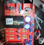
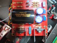
It's time for some new pictures: an overall picture of everything, individual pictures of the BA-3 board and power supply board.
Is the P3 trimmer in each channel centred?
Were you alternating increasing P1 and P2 one turn at a time while watching the offset?
It's time for some new pictures: an overall picture of everything, individual pictures of the BA-3 board and power supply board.
Is the P3 trimmer in each channel centred?
Were you alternating increasing P1 and P2 one turn at a time while watching the offset?
Confirm that your JFETs and your Mosfets are in the right orientation and the right location. Check for cold solder joints. Confirm that your resistors are in the correct locations and that your caps are facing the correct directions.
Also, post a very clear photo of each side of the top and bottom of your board so anyone here can check as well. So 4 pictures. Try to get resistor values if you can, I see you used Dale's. Good stuff.
You can even post a video if you think that will help. Best of luck!
Also, post a very clear photo of each side of the top and bottom of your board so anyone here can check as well. So 4 pictures. Try to get resistor values if you can, I see you used Dale's. Good stuff.
You can even post a video if you think that will help. Best of luck!
Last edited:
see photosI have some experience with biasing and things are not going well. Mostly weird.
As I increase bias to 0.035 ish offset starts to oscillate and I can't get it to dial down.
Then the values on bias and offset both start gyrating with offset over 10.00 DCV.
This is true for both channels.
Turned everything off for now.
Pretty sure I built the amp board correctly. But maybe not.
Of is this a DCV issue?
I get 24 +/- DCV at the PSU.
Attachments

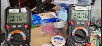
Are you bringing both bias pots up evenly or only raising one? If your R11 is stil lat 0v and you have only raised one trimmer pot then you will get a wacky DC offset like that. Do you have a meter across R10 as well?
The offset isn't exactly the difference between R11 and R10 but a multiple of which is why it can be very touchy to adjust.
The offset isn't exactly the difference between R11 and R10 but a multiple of which is why it can be very touchy to adjust.
Chip, as Ben and Mikerodrig27 have pointed out you need to alternatingly adjust P1 and P2 to bring up the voltage across both R10 and R11. Also, please wait a little between adjustments to allow the voltages to stabilize.
Only when the voltages across R10 and R11 are close will the DC offset be low.
Only when the voltages across R10 and R11 are close will the DC offset be low.
If you measured +-24V at the power supply, you should be able to measure +-24V at the BA-3 board since only six wires are between the BA-3 board and the power supply. Recheck your solder joints.
Rechecked solder points at V+/- and resoldered them on the amp board. I now get 23.8 ~ DCV at V+/- to ground.
Mosfets and Jfets are correct.
I double checked the resistors last week.
I have not touched P3 and they are centered.
I was alternating P1 and P2, though under the circumstances, P2 got active before P1.
Anything before I give it another try?
Dinner time anyway.
Thanks much for the help in debugging.
This is my 2nd BA-3.
I used the PS-22 PSU in my first. Using the Dual/Bipolar LV-Reg here.
I'm using the2SJ313 and 2SK2013 Mosfets with 500R pots. I sourced them from Prakit Premthamkorn.
Different resistors and C3 caps.
It's time for some new pictures: an overall picture of everything, individual pictures of the BA-3 board and power supply board.
Is the P3 trimmer in each channel centred?
Were you alternating increasing P1 and P2 one turn at a time while watching the offset?
Attachments

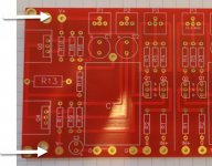
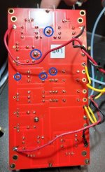
At a quick glance, the center solder pad for one of the JFETs looks to be not soldered in. The rest of the circled are hard to tell but look like cold solder joints.
If your MV reading accross R10 and R11 were within around 10mv, you could expect to see a DC offset of 50-100+ millivolts. It gets out of hand pretty quickly. Address those solder joints with a touch of solder and some heat and give it another shot. I didn't look at the Resistors on the top board but maybe someone else will get that.
Also, everyone here had been extremely supportive with me in the past so no matter what my question was. so long as someone is being positive and trying, others being helpful is all I ever expect. This is a great place for all skill levels.
Attachments
- Home
- Amplifiers
- Pass Labs
- The BA-3 as preamp build guide