Yes, first things first. Please make sure you are getting +/-24V out of your power bipolar power supply and that the V+, GND and V- are properly hooked up.
What Idss grade jfets are you using? The currents look low. Also, have you been playing with P3?
What Idss grade jfets are you using? The currents look low. Also, have you been playing with P3?
I only have the right channel connected to the PSU. I get 24 DCV +/- as you describe at the PSU. I get 24 DCV at V+ and V- on the right channel.J1 and J2 need to be installed which I think I see. Touch ground on the PS board with the black lead of your MM. Red to + you should get 24vdc. to - you should get -24vdc. Tie ground to ground on the linestage, - to - and + to +. If all of that is right, you're not getting anything then it may mean you need to keep turning the turn pot. It takes a lot of turns to get it going.
Ciao @silver89 and thank you for taking so much time and effort to reply to my question, another dear and kind member @ItsAllInMyHead is helping me on the PSU boards and on the I-Select and he's been so kind to ask in the dedicated thread if I could pull enough juice out of the PSU as to power up the board and so far it seems it is no big issue, I will check the pdf you attached and try to understand how it works. molte molte grazie for yours all patienceHi Giovanni,
Sorry for the late reply but it looks like you got some help already. I'm a newb to this DIY stuff and get by with all the help posted on these forums so I'm not too knowledgeable from a technical perspective. With that said, you may not want to take advise from me.... LOL!! But to answer your questions the I-select board can accept 15-30 VDC or 12-22 VAC so I pulled DC from one side of my Broskie Glassware PSU. But you can also choose to pull from the the transformer as well. Board gives relay input switching and ALPs pot mounting in single module which permits source signal isolation, for the most part, to the rear of the chassis. There is also a 12 VDC regulated out for LED or other needs as well. I went this route as it provides a versatile, elegant and simple solution for all my needs. I've used this board in 3 builds (2 x WBA2018 and the BA3 pre) without issue so IMHO does not add much complication to a build. Left a PDF with great info on the board that I pulled from Salas' GB post. Salas is always helpful and the guys in these forums are absolutely awesome so if you need help just ask and post pics. Solutions are a reply or 2 away. Hope that helps. Good luck with your build sir!
Giovanni
Ciao @amandarae thank you for taking time to reply and for your suggestion, my goal is to get the best possible quality with minimum chance to go wrong as I am a total newbie, your suggestion also looks good, can't tell differences on final quality, I can only say that I am not interested into remote, to me the simplest the better but I sure gonna give a look at it, I am still at the initial phase, so far only got (...) the matched MOSFETs for the BA-3, gonna order the board and then start adding passive components while deciding if to go stereo or dual mono route and then picking the PSUs where I am almost set with the help of @ItsAllInMyHead who helped me a lot by deciding onto the Sigma22 board(s) which seem to fit the requirements of both a stereo or dual mono road with our Italian voltage and standard transformers I can retrieve in Europe as to get the necessary voltage to get enough gain to drive the under construction F4.You can also try Muffsy Input Selector. You can view the description here
While I-select is okay, it is manually controlled only. The Muffsy can be controlled manually and remotely.
In my opinion, the advantage of the Muffsy over I-select:
1.) Remote or manually controlled
2.) Requires only 5Vdc that can be had with using just IRM-05-5
3.) Muted preamp to amp signal path
4.) Programmable
5.) Programmable 5V output for Solid State Relay (SSR) that can be used to turn the mains power On and Off
I have two (2) I-Select kits and chose to use the Muffsy instead in my BA-3 because I think it is an elegant source selector.
Grazie mille
Giovanni
I'm just starting a BA-3 preamp build and would like to get some recommendations on a PSU. Cost is a factor but sound quality is the most important thing for me. I'll be using an Antek transformer.
Options:
Cheap lm317/lm337 regulator from eBay
Super Regulator from diyAudio Store
Tubecad/GlassWare LV Regulator
?
Also, I'd like to use a volume control with remote control. Is Muses the way to go? And if so, which implementation? Academy Audio or the board by meldano?
TIA!
Options:
Cheap lm317/lm337 regulator from eBay
Super Regulator from diyAudio Store
Tubecad/GlassWare LV Regulator
?
Also, I'd like to use a volume control with remote control. Is Muses the way to go? And if so, which implementation? Academy Audio or the board by meldano?
TIA!
Superreg or glassware!
Academy audio is prefab, so easier to implement, while Meldanos is raw diy (get parts, solder and sweat), up to your experience/courage/patience
😉
Academy audio is prefab, so easier to implement, while Meldanos is raw diy (get parts, solder and sweat), up to your experience/courage/patience
😉
Superreg is great but can be challenging to get setup and working properly depending on your skill level and knowledge. An LM317/337 is kinda like a Toyota Corolla, reliable...easy to use. Superreg is a Lamborghini Aventador SVJ, a different sort of animal. You will also need to build or buy a raw DC supply since one is not incorporated in the regulator pcb. I have some comments about it here.... https://www.diyaudio.com/community/threads/super-regulator.247281/post-6953315
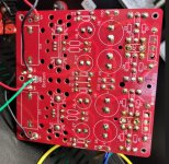
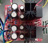
Silver89, could you share with me how you ran the ground leads from the Glassware Bipolar Reg to the BA-3? You also have two leads each coming from V+ and V-, one for each channel, right? Many thanks, just learning….25v. Here are a few pics of my build
Vincent
Hello jhuabd,
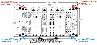
in the BA-3-frontend the connections from the symmetrical PSU to the board are like in the pic
below.
You have to connect both channels to the PSU = 6 wires
V+ / V- / ground and this for left and right channel.
Cheers
Dirk
in the BA-3-frontend the connections from the symmetrical PSU to the board are like in the pic
below.
You have to connect both channels to the PSU = 6 wires
V+ / V- / ground and this for left and right channel.
Cheers
Dirk
Attachments
Ciao @amandarae thank you for taking time to reply and for your suggestion, my goal is to get the best possible quality with minimum chance to go wrong as I am a total newbie, your suggestion also looks good, can't tell differences on final quality, I can only say that I am not interested into remote, to me the simplest the better but I sure gonna give a look at it, I am still at the initial phase, so far only got (...) the matched MOSFETs for the BA-3, gonna order the board and then start adding passive components while deciding if to go stereo or dual mono route and then picking the PSUs where I am almost set with the help of @ItsAllInMyHead who helped me a lot by deciding onto the Sigma22 board(s) which seem to fit the requirements of both a stereo or dual mono road with our Italian voltage and standard transformers I can retrieve in Europe as to get the necessary voltage to get enough gain to drive the under construction F4.
Grazie mille
Giovanni
I am also using Sigma 22 set at +- 30Vdc. Easy to build and barely warm to the touch after several hours powering the BA3. I like it! Enjoy your build.

Yes, of course, thank you!Hello jhuabd,
in the BA-3-frontend the connections from the symmetrical PSU to the board are like in the pic
below.
You have to connect both channels to the PSU = 6 wires
V+ / V- / ground and this for left and right channel.
Cheers
Dirk
Hi Folks,
Very nice thread. Like many of you I use the Muses volume control board. Mine is coming from Academy audio and is working very nicely with Wayne's BA 2018 linestage.
As per application note from Academy Audio, the error level can be reduced by increasing the preamp input impedance. Here is a screenshot from the Application note and the link to the full document.

https://www.academyaudio.com/_files/ugd/6fd7ca_be4a3abc142e448587231feaa445cf51.pdf
Do you see any potential impact on the sound quality or stability of the BA-3 if I increase the R2 resistor from 47k to 470k?
Thanks.
Very nice thread. Like many of you I use the Muses volume control board. Mine is coming from Academy audio and is working very nicely with Wayne's BA 2018 linestage.
As per application note from Academy Audio, the error level can be reduced by increasing the preamp input impedance. Here is a screenshot from the Application note and the link to the full document.
https://www.academyaudio.com/_files/ugd/6fd7ca_be4a3abc142e448587231feaa445cf51.pdf
Do you see any potential impact on the sound quality or stability of the BA-3 if I increase the R2 resistor from 47k to 470k?
Thanks.
Ciao Amanda,
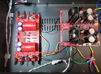
thank you for your reply, I can see you using the Sigma 22 and, actually, I'd like you to give me a short description, as I stress each and every time as a total newbie it is also about to learn so, I can see a transformer feeding the Sigma 22 and another one feeding what it might be a Sigma 11, the BA-3 board up there on the left, bottom left is that the input switch?
No clue what the relay switch is for nor what the board in between it and the apparently switch board is, also top right before switch command and in the corner between the BA-3 board and the other PSU.
By the way, you all make the thing look easy and are great help and support, am not confident yet I can make it but I am sure you will be following me and not because I'll get you a beer once you come through my place ;-)
Grazie
Giovanni
I get +/- 24V out of the PSU and into the amp board. I'm using 8 -10 IDSS jfets from diyaudio store. I have not touched the P3 pots.Yes, first things first. Please make sure you are getting +/-24V out of your power bipolar power supply and that the V+, GND and V- are properly hooked up.
What Idss grade jfets are you using? The currents look low. Also, have you been playing with P3?
I built a new board with the FQP3P20/30 mosfets and 500R trimpots. And I get the same results - no current flowing. Something is amiss. This is the second BA-3 preamp I've built. The only difference is I'm using the Dual/Bipolar LV Reg PSU instead of the PS-22 PSU. I'm missing something in how I've wired between the PSU and the amp card.
Attachments
I built a new board with the FQP3P20/30 mosfets and 500R trimpots.
As documented in the BA3 article, the Fairchild parts require higher Vgs voltage to turn on (when compared the Toshiba mosfets) so you likely need 1K trim pots.
If you have the COM probe of your multimeter on GND of the BA3 board and measure with the other probe +24V on V+ and -24V on V- (again on the BA3 board) then your power supply wiring is correct.
Ciao Amanda,
thank you for your reply, I can see you using the Sigma 22 and, actually, I'd like you to give me a short description, as I stress each and every time as a total newbie it is also about to learn so, I can see a transformer feeding the Sigma 22 and another one feeding what it might be a Sigma 11, the BA-3 board up there on the left, bottom left is that the input switch?
By the way, you all make the thing look easy and are great help and support, am not confident yet I can make it but I am sure you will be following me and not because I'll get you a beer once you come through my place ;-)
Grazie
Giovanni,
Hi Giovanni,
I can see a transformer feeding the Sigma 22 and another one feeding what it might be a Sigma 11, the BA-3 board up there on the left,
The small transformer feeds the VRDN (please search Pass Labs forum) to get a regulated DC of +-15 Vdc to power the Muses,
the smaller board immediately to the left of it is to get 5Vdc from the output of the VRDN for the Adafruit display of the Muses volume control.
No clue what the relay switch is for nor what the board in between it and the apparently switch board is, also top right before switch command and in the corner between the BA-3 board and the other PSU.
The relay (SSR-40, Solid State Relay) is to use the 5V SSR out of the Muffsy to turn On/Off the "big" and "small" transformer and in turn, turns On the VRDN and the Sigma 22, then the volume control and the BA-3; the board between the relay and the Muffsy is the IRM 5-02 which converts 120 Vac line voltage to +5Vdc to power the Muffsy input selector.
The top right switch, is not a switch but just a pcb that I use to implement the LED input display for the Muffsy below
So, I will try my best to explain how the system operates.
Looking at the back of the preamp, a little cut off from the picture but visible, to the right of the RCA output is the main switch for line 120 VAC. This switch turns On and Off only the IRM-5-02 (On is standby, Off is totally disconnected from line voltage). When the switch is on standby, the IRM has 5V out, the Muffsy control board can be turn On by pressing the encoder switch on the faceplate of the preamp. When the Muffsy is awake, it triggers the relay, then it connects the transformers to the line voltage, then it powers the boards and so on as I described above.
Hope my description make sense.
On a lighter note, lots of knowledgeable people here to answer your questions when you build the preamp, I know because I asked a lot of questions too.
Hi Chip,I get +/- 24V out of the PSU and into the amp board. I'm using 8 -10 IDSS jfets from diyaudio store. I have not touched the P3 pots.
I built a new board with the FQP3P20/30 mosfets and 500R trimpots. And I get the same results - no current flowing. Something is amiss. This is the second BA-3 preamp I've built. The only difference is I'm using the Dual/Bipolar LV Reg PSU instead of the PS-22 PSU. I'm missing something in how I've wired between the PSU and the amp card.
Pardon me, and maybe you know this already but just in case. You are aware that it takes approximately 3-4 complete revolutions of either P1 or P2 before you can see an output at R10 or R11 right?
Good point amanadrae.
Chiptech, when you wrote you couldn't get things to bias up, did you in fact turn them all the way up and still got nothing?
Chiptech, when you wrote you couldn't get things to bias up, did you in fact turn them all the way up and still got nothing?
Yes I turned both of the pots all the way up. If only it was that simple. Thanks.Hi Chip,
Pardon me, and maybe you know this already but just in case. You are aware that it takes approximately 3-4 complete revolutions of either P1 or P2 before you can see an output at R10 or R11 right?
I think you might be on to something. On the right channel I get -24DCV but not on V+. On the left channel, I get +24DCV but not at V-.As documented in the BA3 article, the Fairchild parts require higher Vgs voltage to turn on (when compared the Toshiba mosfets) so you likely need 1K trim pots.
If you have the COM probe of your multimeter on GND of the BA3 board and measure with the other probe +24V on V+ and -24V on V- (again on the BA3 board) then your power supply wiring is correct.
Which seems weird but points back to the PSU board.
Maybe time for a new PSU board. The PS-22 has been out of stock for months.
- Home
- Amplifiers
- Pass Labs
- The BA-3 as preamp build guide