Thanks Jim.
I'm Billy. So far I've built an F5 and an 834 phono stage. Frugal horns and a heavily modded Lenco TT. But... I had a pretty severe stroke in 2018 and I get big brain farts. Leading to confusion.
This forum feels like a place where I can get good advice.
I'm Billy. So far I've built an F5 and an 834 phono stage. Frugal horns and a heavily modded Lenco TT. But... I had a pretty severe stroke in 2018 and I get big brain farts. Leading to confusion.
This forum feels like a place where I can get good advice.
just heal
in time you'll feel that stupidity is not just allowed and tolerated, but is one of requirements to be a member here
ZM, still Undisputed in Dumbness, around

in time you'll feel that stupidity is not just allowed and tolerated, but is one of requirements to be a member here
ZM, still Undisputed in Dumbness, around
What min corrent ? and this?1PC LT1083CP Sliding Type High Power Adjustable Voltage Power Supply Board | eBay
That only gives you a single polarity. you need something that can give
+/-24V (or more).
Each channel draws about 60mA or so. The LM317/337 one should work nicely.
+/-24V (or more).
Each channel draws about 60mA or so. The LM317/337 one should work nicely.
I'm looking at the LM317/337 as well.
I have a question. I have a tx with dual 24v outputs but all the boards seem to be designed for centre tapped transformers. I'm stuck about what to do. Is it as simple as plugging two wires into ground?
I have a question. I have a tx with dual 24v outputs but all the boards seem to be designed for centre tapped transformers. I'm stuck about what to do. Is it as simple as plugging two wires into ground?
I believe everything should be clear if you read datasheet of xformer
having separate secondaries and connecting them to have CT is much easier that the other way around
here's some help
ignore miss-type here and there
if you have datasheet, post it here
having separate secondaries and connecting them to have CT is much easier that the other way around
here's some help
ignore miss-type here and there
if you have datasheet, post it here
Attachments
Last edited:
duh
no color info there
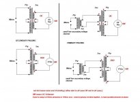
what wire colors you have , one secondary, second secondary?
usually, start of winding is one color, end of winding other color
say that you have green and yellow
green 1 : first secondary out (to diode bridge)
yellow 1 + green 2 : Center Tap (GND)
yellow 2 : second secondary out (to diode bridge)
checking is easy , by sketch I uploaded ; connect two wires from different secondaries, put Vac meter across free ends,power up Donut ( taking all safety measures - isolated mains contacts etc.), measure ; if you have double Vac , that's the arrangement ; if you have nearly 0Vac , change place of wires of one secondary, retest
no color info there
what wire colors you have , one secondary, second secondary?
usually, start of winding is one color, end of winding other color
say that you have green and yellow
green 1 : first secondary out (to diode bridge)
yellow 1 + green 2 : Center Tap (GND)
yellow 2 : second secondary out (to diode bridge)
checking is easy , by sketch I uploaded ; connect two wires from different secondaries, put Vac meter across free ends,power up Donut ( taking all safety measures - isolated mains contacts etc.), measure ; if you have double Vac , that's the arrangement ; if you have nearly 0Vac , change place of wires of one secondary, retest
duh
no color info there
what wire colors you have , one secondary, second secondary?
usually, start of winding is one color, end of winding other color
say that you have green and yellow
green 1 : first secondary out (to diode bridge)
yellow 1 + green 2 : Center Tap (GND)
yellow 2 : second secondary out (to diode bridge)
checking is easy , by sketch I uploaded ; connect two wires from different secondaries, put Vac meter across free ends,power up Donut ( taking all safety measures - isolated mains contacts etc.), measure ; if you have double Vac , that's the arrangement ; if you have nearly 0Vac , change place of wires of one secondary, retest
I understand. Thank you.
😀
They are ClarityCap CSA bought at HiFiCollective.
I went ahead and put these caps on the outputs of both my Pearl 2 and BA-3 FE, replacing the electrolytics and film bypass. 2.2 uF is all I need based on input impedances. I listened for a few minutes and my initial impression is positive, I'll try to do a longer session tonight.
Don't laugh at my BA-3, I mistakenly bought components that are oversize and crammed them in. 😛
What os the best regulator?
This
Class A Parallel Regulated Power Supply Finished Board | eBay
Or this?
AC/DC 12V 24V LM317 LM337 Linear Voltage Regulator Adjustable Power Supply Kits 699951021662 | eBay
Thanks
This
Class A Parallel Regulated Power Supply Finished Board | eBay
Or this?
AC/DC 12V 24V LM317 LM337 Linear Voltage Regulator Adjustable Power Supply Kits 699951021662 | eBay
Thanks
What os the best regulator?
This
Class A Parallel Regulated Power Supply Finished Board | eBay
Or this?
AC/DC 12V 24V LM317 LM337 Linear Voltage Regulator Adjustable Power Supply Kits 699951021662 | eBay
Thanks
The first one has no description. The second one would work, I use a similar one: WZ-4 LM317/LM337 Adjustable Regulated Power Supply Board | eBay
Another choice. This one works well in my BA3pre.
Class A Parallel Adjustable Regulated Power Supply DIY Kits output +-5V ~ +-20V 783710087645 | eBay
Class A Parallel Adjustable Regulated Power Supply DIY Kits output +-5V ~ +-20V 783710087645 | eBay
- Home
- Amplifiers
- Pass Labs
- The BA-3 as preamp build guide