Do what 6L6 said above. The bypass cap is trivial, it might get you that last .000001% improvement you are looking for or it might make things worse. Build the preamp first and see if you like it, the character of the preamp is not affected by the bypass cap. You will either like it or you won't, passive parts like resistors and capacitors will never change that.
I would recommend putting some wire leads and trying a few different capacitors in the C3 spot. They all sounded very different in my system.Wow, 6L6 thanks for the quick reply. On the film cap bypass, it was kind of a rage on loudspeaker passive crossovers and some combinations of capacitors enhanced or were synergistic to the final sound. Maybe my 70-year-old mind is failing me in thinking I read discussions on this thread. Your feedback is much appreciated.
And I haven't tried it in this circuit, but I've never liked a bypass cap when I tried. I bought some top end duelands to do it in an amp, but just thought it blurred the sound.

I did leads and clips for a month and subbed in four different caps (2x mundorf, miflex, and Jupiter)... different tonalities, colors, and soundstaging. Very easily discernable and you can change them out painlessly that way.Great idea on the leads for experimentation, maybe I'll go that route. I did it once on a small two-way loudspeaker and to this day I think it had the most natural vocal/speech I ever heard. Head turning, who's in the room kind of experience
Worth it to experiment and spend to upgrade in the position from my seat.
Have you tried it with no output capacitor?I would recommend putting some wire leads and trying a few different capacitors in the C3 spot.
I'm too dumb to know that was advisableHave you tried it with no output capacitor?
What’s your DC offset before the output cap on the BA-3?
What’s your DC offset at the output speaker terminals of the F4?
Perhaps answering those questions will help in making a decision on the necessity of using an output capacitor on the BA-3.
But like you say, the output cap on the BA-3 affords you an opportunity to flavor the BA-3 in addition to using the pot on the BA-3 (with a distortion analyzer).
Enjoy!
Best,
Anand.
Re: Distortions, I was wondering if/how the H2 H3 were put to balance? lowest distortion? or anything cap-relative? (Cap XY prefers lower, Cap YZ a bit higher H2H3)?
I’m not sure it’s “advisable” but I did it quite a few years ago. If you start reading HERE you’ll see a discussion on the subject. I had input transformers installed on the amp I was using so I felt reasonably safe pulling to output capacitors on the BA-3 board.I'm too dumb to know that was advisable
This brings a question to mind…how much DC on the input of an amplifier does it take to do damage? For the sake of discussion let’s say the amplifier is an F5.
@KevinHeem
First you have to know the closed loop gain of the F5, which as I recall is about 15dB which is about 5.6X. This is because DC on the input is amplified.
My general rule of thumb is to avoid +/-1V DC on the speaker outputs. This coincides with commercial speaker protection circuits available, they engage their circuit at least at 700mV DC and above.
DC can overheat voice coils of tweeters, displace the cone (damaging the suspension, etc….), reduce efficiency and even cause irreversible damage. It doesn’t happen often but it can. I have heard DC output from a speaker, it doesn’t sound great. In fact, it sounds like distortion. This becomes even more audible the more sensitive the speaker is.
So basically if you take +/-1V DC as the maximum on the output, that means you shouldn’t have more than +/-180mV DC on the input of an F5.
Best,
Anand.
Thank you for the explanation Anand, now that I think about it, an amplifier like the F5 probably doesn't care what it's amplifying (AC or DC). So, the only thing we're concerned about is DC hitting and damaging the speakers. In reading the manual the "open loop gain" is 15dB. So hypothetically you could connect a DC power supply to the input of an F5 and get 5.6 x whatever DC voltage you put in? There would be limiting factors of course, and I'm trying to understand what they would be? This is good thing, it's forcing me to re-read the F5 manual and study about amplifiers in general. In actuality I have very limited knowledge of how these circuits work...I mean, I can build this stuff but my understanding of how they work is at the novice level at best. Thanks again for engaging in the conversation and helping answer my odd questions.
Also, I hope no one took my earlier comment to mean that it's a good idea to just pull the output capacitors from a preamplifier and run it that way. I tried it with the BA-3 under what I considered to by fairly safe and controlled conditions, but I'm not recommending it to everyone.
Also, I hope no one took my earlier comment to mean that it's a good idea to just pull the output capacitors from a preamplifier and run it that way. I tried it with the BA-3 under what I considered to by fairly safe and controlled conditions, but I'm not recommending it to everyone.
Last edited:
Nothing "dumb" about it. Be "advised" I'm inclined to do things that are not (advisable).I'm too dumb to know that was advisable
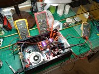
Guys, finished up the build and spent the last 4 hours focused on the bias and offset settings. I would like your input on my results based on your experiences. The following is where I ended up:
Right Channel - P1 (R11) 1.015V P2 (R10) 1.016 Offset .001V
Left Channel - P1 (R11) 1.00V P2 (R10) 1.00V Offset .004V
On both channels, they cooked for over an hour each and inputs were shorted.
Thanks for your help getting to this point and input.
Chris
Right Channel - P1 (R11) 1.015V P2 (R10) 1.016 Offset .001V
Left Channel - P1 (R11) 1.00V P2 (R10) 1.00V Offset .004V
On both channels, they cooked for over an hour each and inputs were shorted.
Thanks for your help getting to this point and input.
Chris
Attachments
Very good. If you didn’t do the hard part yet, you need to now. Put the lid on, let it cook for an hour, then check offset an Iq again. If you allready did that, results are perfect - job extremely well done!
However, I find pushing the Iq yields very good results. I’d push for 55mA, approx 1v2 drop across 22R. Depending in your rail voltage. If 32v, keep at 45mA, if less, it is safe to push a bit without any other changes.
Edit: your sinks are sissysmall, like Papas. If upping Iq, beware of temp.
Regards,
Andy
Thanks Andy,
I am using a 24V supply and after letting it cook with the top on nothing seemed to be terribly out of wack. Once you start tweaking it never ends and now the left channel is at P1 9.99V P2 9.98V offset is now at .009V and I have not switched the probes to check the right channel. Is there a point you just stop playing with it? Will it ever just lock in or is there a range that is acceptable?
Chris
Another thought, would larger heat sinks better stabilize things? The temps don't seem terribly high with a digital thermometer maybe a high of 115 degrees to 99 degrees
Everything you write seems just terribly fine, Chris! 10mV is nothing, the cap takes care of it. At this point I would give it a listen and use it for a while, and rather tweak later if you want to experiment. It is very touchy yes 
- Home
- Amplifiers
- Pass Labs
- The BA-3 as preamp build guide