It looks like you have a double primary (wired in parallel for US 115V) double secondary transformer, a NTC as inrush limiter. From what I can see:
- Do you have a fuse somewhere - maybe in the IEC socket?
- Is the chassis grounded?
- to avoid ground loops, Pa often puts a NTC or diode bridge between signal/PSU ground and chassis/earth ground
Yep, fuse in the IEC socket and chassis is grounded to IEC ground as well. I should look more into the NTC/diode separator, thanks!
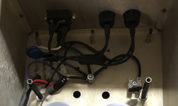
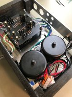
This is a peek into one of my amps showing the IEC and chassis "star" ground connection. The purple wire connected there is the electrostatic shield wire from my Antek transformer. On the right side is the CL-60 NTC that gives some isolation between my audio circuit ground and this safety ground. (No wire connected to it in this picture because I was in the middle of a rebuild when this was taken... )
Attachments
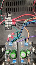
Ok. Added a star ground inline with a CL-60 to earth ground. Here's my power lineup:
IEC Red > CL-60 > On-off switch > Red transformer primaries.
IEC Black > Black transformer primaries.
IEC Ground > Ultrabib grounds; CL-60 to star (BA-3 grounds and transformer shield wire)
Each transformer secondary goes solely to one bib board (checked for continuity)
Prior to connecting the secondaries, I tested the bibs with my variac and everything worked perfectly.
Connected the secondaries, zero volts. Transformer not conducting. 110 in, 0 out. I am so far beyond lost.
Attachments
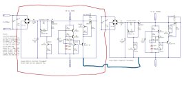
Transformer secondary phasing problem? Swap the blue and green wires on the positive reg.
Your grounding scheme needs help there. I still see direct continuity between the uBiB grounds and the IEC ground. The IEC ground should always go straight to the chassis (actual metal, not paint), preferably very close to the IEC connector itself. And I use star washers and lock washers to make sure that connection never gets loose. Now, your audio circuit (BA-3) ground wires should go to the uBiB ground, NOT chassis. We want the CL-60 between the audio circuit ground and the chassis ground connection. You should be able to measure ~10 ohms between those two grounds when you get it right.
Your grounding scheme needs help there. I still see direct continuity between the uBiB grounds and the IEC ground. The IEC ground should always go straight to the chassis (actual metal, not paint), preferably very close to the IEC connector itself. And I use star washers and lock washers to make sure that connection never gets loose. Now, your audio circuit (BA-3) ground wires should go to the uBiB ground, NOT chassis. We want the CL-60 between the audio circuit ground and the chassis ground connection. You should be able to measure ~10 ohms between those two grounds when you get it right.
Sounds like the second transformer is also shot. You could verify out of circuit by measuring resistance across each winding, which should read very little OHMs and resistance from winding to winding should read infinite.Transformer not conducting. 110 in, 0 out
The fuse is much too big, if it allows the transformer to melt itself. I'd recommend getting the light bulb current limiter and checking everything step by step before turning everything on without safety net. Luckily those small transformers aren't too expensive and I'd consider it educational money.
You'll get this - we've all been there.


Yeah, I'm gonna get the light bulb setup today. I don't mind paying for education, but the shipping time kills me!
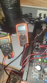
I've swapped the secondary phase and started reworking the ground. I have a 5A/125V fuse installed, but will replace with a 1A when they get here. Out of morbid curiosity, I checked my IEC/fuse connections and with the fuse removed, I'm still reading 20VAC out of the fuse holder (110 applied by variac). Might consider replacing the holder while I'm at it.
Thanks for your help! I was ready to start flipping tables last night lol!
Attachments
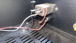
Some heatshrink on AC mains connections like that is a wise practice... Look at my picture at #2883. In fact that might even be doubled up, two layers. Just hate seeing exposed HV terminals like your picture.. those can bite you for sure.. Safety first.
What's the VA rating of your transformer? A rule of thumb is to fuse at ~(VA rating/ AC input rating). So if you're using a 25VA transformer and you're in North America (120VAC) then start at perhaps 1/4A.
In general, you want to fuse as low as possible while avoiding nuisance blown fuses from transient events like start up surges.
In general, you want to fuse as low as possible while avoiding nuisance blown fuses from transient events like start up surges.
100VA. I had grand schemes of powering my Pearl 2 from it, but I wound up getting a little separate transformer for it (25VA, 22V).
And I'll get the HV terminals re-covered, they're just uncovered for photos.
And I'll get the HV terminals re-covered, they're just uncovered for photos.
I would think burning out the secondaries in a transformer would occur with some sort of fanfare. Buzzing , humming, smoke ? Even a somewhat smaller mains transformer. Are you experiencing this type of occurrence ?
When commenting earlier I was perplexed that you had in fact lost the secondaries without mentioning some sort of drama along with the occurance.
Again , if I were faced with this.... I would Break connections before and after the power supply board but leave everything physically mounted. Then look for a short to ground at all points (secondaries, input of PS , output of PS , power input of BA3). Then test and reconnect items one at a time and retest.
Anyone who really works with electronic troubleshooting knows that the simple mistakes can really get you. It's easy to hyper-focus on the more complicated stuff and overlook an easy problem staring you in the face.I
Best of luck....keep plugging away.
^^ This.
@Alypius
Remove the secondaries from the BiBs. Measure and verify continuity from each secondary’s lead wire to it’s trail.
If you’ve got the proper windings paired up, then turn it on, and (very carefully, of course) measure the AC volts on the transformer primary, and then repeat for each secondary.
At #2876 he's talking about burning hot rectifiers and an aroma, with another replacement transformer.. I agree with 6L6. I would get that transformer isolated and sort these windings out first.without mentioning some sort of drama...
At #2876 he's talking about burning hot rectifiers and an aroma, with another replacement transformer..
Yes, but that could be the BIBs, not the transformer. …? Maybe? Dunno.
Yep. This one is weird enough that we pretty much need to start at the fuse and work forward.I agree with 6L6. I would get that transformer isolated and sort these windings out first.
He has the short figured out already.So it turns out that I need one secondary winding per bib board; using just one for both pos and neg winds up shorting the rectifier diodes.
Attachments
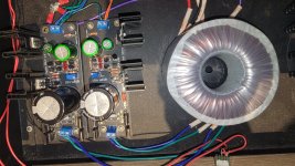
Okay, been a long day but here's what I have so far:
-Reworked the grounds.
IEC > chassis/star
BA-3 > BiB (cross-connected) > CL-60 > chassis/star
Transformer > chassis/star (when reinstalled)
-Separated components for ground test, then reconnected BiB to chassis, then BA-3 to BiB. None found.
-Transformer works on the bench. 115V in, 24 out on both windings. All resistances as expected. (Yay!)
Tonight/tomorrow:
-Install 1A fuses on delivery.
-Build light bulb tester. Test each primary on the terminal board before connecting to BiBs. Connect to BiBs with dummy load at the DC out, then reconnect BA-3.
The spectacular failures were only with the shorted diodes (#2880). Everything else has simply been no voltage.
Thanks again! If you're in VA, swing by and I'll smoke meats and brew beer.
Attachments

It's alive! After a long afternoon of measuring and headscratching, I replaced the fuse holder and terminal board. There was some heavy pitting and corrosion from spending years next to the beach, so I figured that might've caused some issues, even if intermittently. Long story short, everything works perfectly and the BA-3 is happily baking for biasing. And yes, it's next to a tower fan. Sigh.
Next up: redo power supply for Pearl 2; start work on F4 (I have Aleph J boards but the consensus seems to be F4 pairs better with the BA-3), finish Whammy when my chassis arrive.
Thank you to everyone for your patience with this incredibly frustrating troubleshooting!
Next up: redo power supply for Pearl 2; start work on F4 (I have Aleph J boards but the consensus seems to be F4 pairs better with the BA-3), finish Whammy when my chassis arrive.
Thank you to everyone for your patience with this incredibly frustrating troubleshooting!
Attachments
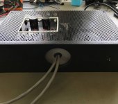
Speaking of power supplies... this is an outboard ±45Vdc pseudo dual mono supply I've nearly completed for an upcoming project. This chassis is a little hacked up due to being used for about three other abandoned / mothballed projects already.. Not the prettiest thing but this won't be seen anyhow in my system due to how things are arranged, it just needs to function properly.
Attachments

- Home
- Amplifiers
- Pass Labs
- The BA-3 as preamp build guide