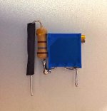
If you are don't feel like waiting for a part to show up, you can run a resistor in series with the trimmer pot. Something like a 200-500 ohm. Be careful with a 5k. It would likely be pretty touchy to adjust compared to a 1k or a trimmer and resistor.
Attachments
Yeah, the zeroing process reminded me of that lol. Got some 1k's on order, should be here Tuesday. I have a couple of other projects to keep me occupied until then!

Sigh. Got the whole thing set up on the test bench and connected to my DC power supply; both sides biased to about 0.8VDC at 0 offset. Disconnected and installed in the chassis and the ultrabibs.
And now is when things go haywire. One side has about .125VDC bias with a waterfall offset: it starts at zero, climbs to 400mV, then resets to zero and starts again. The other side has the same bias but 3VDC offset and the pots don't do anything.
Turned off and examined the board and wires, nothing amiss. Reenergized, and now none of the bibs conduct (OVDC, no LEDs). No power from the transformer. Proper AC all the way to the inputs, zero coming out.
Please post a series of well-lit, in-focus photos. Let's put the hive mind to it and see what we can see. 🙂
I can't tell from here if your problem is the uBiB, or the BA-3. I guess my crystal ball is way too hazy... Will the power supply provide the correct voltages if it's just powering some dumb power resistors? Those resistor values chosen to closely simulate your actual load of course... BA-3 as designed draws ~50mA per rail, per channel, correct? (24V rail, .050 amps, use ohm's law, R=E/I... yada yada..)
*edit - you have proper AC voltage going to the bridge rectifier, but no DC voltage at C1 of the uBiB? uBiB failure drama might be better solved with help in the uBiB thread..
*edit - you have proper AC voltage going to the bridge rectifier, but no DC voltage at C1 of the uBiB? uBiB failure drama might be better solved with help in the uBiB thread..
Last edited:
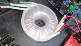
No, it's zero volts going into the bibs. I'm pretty sure it's the transformer; I isolated it last night with mains in, zero out. There are micro-tears in the wrapping, so it got banged around during my move. Got another one on order, so we'll see.
I might hook up the monster AS-4218 I have in the closet for my F-4 build just to make sure there's no damage to the bibs. Tonight I'll hook up the DC supply to the BA-3 while in the chassis and redo the biasing.
I might hook up the monster AS-4218 I have in the closet for my F-4 build just to make sure there's no damage to the bibs. Tonight I'll hook up the DC supply to the BA-3 while in the chassis and redo the biasing.
Attachments
Is the fuse OK?
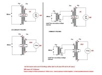
Just to verify, you have AC at the primaries of the transformers but nothing at the secondaries?
BTW, how large is that transformer?
Just to verify, you have AC at the primaries of the transformers but nothing at the secondaries?
BTW, how large is that transformer?
Lol yep! Fuse etc are fine. I isolated the xfmr (AS-1222: 100VA, 22V), connected directly to variac. All the volts going in, nothing coming out.
ETA: yes, in=red/black, out=blue/green. 😛
ETA: yes, in=red/black, out=blue/green. 😛
Last edited:
If it's a dead transformer, do you know what might have caused it?
The worry of course is whatever caused the first to fail might damage your replacement.
The worry of course is whatever caused the first to fail might damage your replacement.
Yep, pulled it out of the chassis onto the test bench, variac to primaries and ground, DMM to secondaries. Ded.
On the plus side, the BA-3 is rebiased successfully and I'm almost done with my Whammy! Just gotta wait for the new transformer to get here.
On the plus side, the BA-3 is rebiased successfully and I'm almost done with my Whammy! Just gotta wait for the new transformer to get here.
Could be primary wire of transformer that has broken?
Did you measure primary / secondary just using an ohm-meter (DMM) to measure the impedance of those?
Did you measure primary / secondary just using an ohm-meter (DMM) to measure the impedance of those?
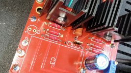
So good news: new transformer arrived, is installed, and we have power again!
Bad news: the ultrabibs are really unhappy in their home. Even with the BA-3 biased (more or less; it's set to .8V with a slowly increasing offset as it bakes off my power supply), half the rectifiers are doing their darnedest to smoke themselves (yes, I'm using the correct secondaries). I have mains power applied for about fifteen seconds before I get that tell-tale aroma and cut the power. Once I get things buttoned-up, I'll post over at the ultrabib thread.
Bad news: the ultrabibs are really unhappy in their home. Even with the BA-3 biased (more or less; it's set to .8V with a slowly increasing offset as it bakes off my power supply), half the rectifiers are doing their darnedest to smoke themselves (yes, I'm using the correct secondaries). I have mains power applied for about fifteen seconds before I get that tell-tale aroma and cut the power. Once I get things buttoned-up, I'll post over at the ultrabib thread.
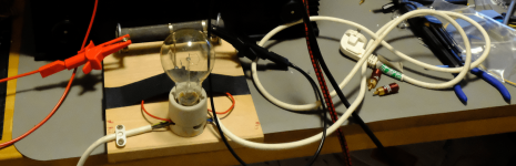
Maybe you could place a good old 40 W light bulb in series with the transformer primary to prevent further damage whilst searching for the short/error.The worry of course is whatever caused the first to fail might damage your replacement.
Attachments
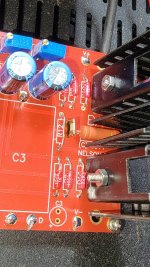
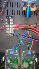
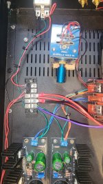
So it turns out that I need one secondary winding per bib board; using just one for both pos and neg winds up shorting the rectifier diodes. So now I worry about any other issues with my power setup, mainly with the grounds.
I have AC going to a terminal board, controlled by a switch before going to the transformer. All grounds go to the bottom right of the terminal board then to IEC ground. Anything wrong with this setup?
I have AC going to a terminal board, controlled by a switch before going to the transformer. All grounds go to the bottom right of the terminal board then to IEC ground. Anything wrong with this setup?
Attachments
- Home
- Amplifiers
- Pass Labs
- The BA-3 as preamp build guide