More insight and mistery solving.
I am back home guys. 🙂
I can give some insight about R50, AKA "the magic resistor", through a confession.
The red PCB, which has now JFET input + MPSA18 VAS, was not entirely satisfying , as you perhaps remember, mainly because of a want of mid-bass (and deep bass) but on the good part was it had more color and textures, more focused sound (which I thought was due because of the JFETs), with a negative counterpart in "tighter" sound presentation. When I did the swap for the MPSA18 I realized that the cascoded VAS mod, which was nearly a year ago, included a 22R (not a 47R which I completely lacked) RPR resistor, which is an "audiophile" resistor. Thankfully, I made the upgrade in two steps, and believe me, my physical configuration is always a PIA to resolve, so now I can evaluate better the individual effect of both parts.
I swapped the 22R RPR for an identical 47R metal film (I don't remember if 50ppp or 100ppm) cheap resistor as in the "ALLBJT" amp, and I can assure you that the effect of this very important R50 resistor is evident. Not even burned-in (solder) the deep bass and the mid-bass both appeared, also the "tightness" is gone and there is more ampleur to the sound, it is more relaxed, while keeping its beloved dynamic presentation. So 47R (E12) or 46.4(E48) should be considered optimal, as per Peufeu's work and Hans' calculation. Further listening is needed though, but I wanted to tell my initial findings.
The esoteric part of the discussion is that I strongly believe that one can use R50 to "voice" the amp, if one considers to do so, or to make it more "transparent".
For example, choose Holco black 5ppm metal film resistors, which are "neutral" or "cold" sounding, for the input CFP (R7-8 R24-25; JOSI1's schematic) and degenerator resistors (R9-10 JOSI1's schematic) and vary R50 (which BTW is R28 on JOSI1's schematic) depending on the desired effect: Caddock Thick film resistor non inductive and non capacitive, or other low noise R, for a transparent non-effect, OR your preferred "color" like for example, using RPR which makes warmer but textured and detailed sound...etc. Resistor swap is welcome.
I have here some Japanese Riken Ohm carbon film resistors whose effect is to make any circuit sound like your grandpa's tube radio, I swear 😀 On the other hand, I can build my own DIY non inductive, non capacitive, low noise resistor with Manganin in honeycomb configuration, as I do for my DAC I/V resistors. That gives me the most transparent sound. 😀 But that is only for hardcore DIYers...
So there you are, as the VAS transistor, the R50(R28) is also critical to sound quality and worthy of experimentation.
Cheers,
M
Last edited:
Hi Max,
just an observation which occured to me a few weeks ago is that the Magic Resistor
is trying to keep the VAS driver operating at constant power. and this is a very simple
way to do this.
The JFET in the input stage is doing similar job, I just wonder if magic resistor would
help here as well. I've not experimented with this in simulation yet, but might help
the BJT version.
Regards,
Symon
Hi Max,
good to hear that you are back.
In the meantime I performed some tests with my prototype
square wave +-20V / 20kHz @ +-32V power supply
input filter 1k/220pF
My test amp runs stable with the JFET input and both AllBJT versions
(2 and 4 BJTs) shown in your post #503 and included in my latest schematic
So we should use my latest schematic for a first layout
For the JFET version 2 gate stoppers (330R SMD 0805) were added.
For the allBJT versions 4 Caps (10-100n SMD 0805 ) parallel to the LEDs were added (no place for R/C)
Output stage
I replaced the zener diodes of the driver stage by
a LED string and precision reference LM329 (6.9V @ 0.5 - 15mA)
both with no influence on stability.
May be there's a difference in sound.
I will soon post my final proposal for a first layout.
Cheers
good to hear that you are back.
In the meantime I performed some tests with my prototype
square wave +-20V / 20kHz @ +-32V power supply
input filter 1k/220pF
The only one that works and is stable is my recommended "version 1", which has only 2 extra BJTs, each to feed a pair of equally bootstrapped BJTs, with its bases connected to the common node, previous to emitter degeneration resistors (100R; and 20R on Hans oprional version) with all other versions failing badly on the square wave test for reasons unknown to me at this time. Even the recommended "version 1" fails when one adds a couple of extra BJTs to make subcircuits completelly independent from each other...
My test amp runs stable with the JFET input and both AllBJT versions
(2 and 4 BJTs) shown in your post #503 and included in my latest schematic
So we should use my latest schematic for a first layout
For the JFET version 2 gate stoppers (330R SMD 0805) were added.
For the allBJT versions 4 Caps (10-100n SMD 0805 ) parallel to the LEDs were added (no place for R/C)
Output stage
I replaced the zener diodes of the driver stage by
a LED string and precision reference LM329 (6.9V @ 0.5 - 15mA)
both with no influence on stability.
May be there's a difference in sound.
I will soon post my final proposal for a first layout.
Cheers
Excellent, guys. I see the spirit is up!
Comments inside.
Best wishes,
M.
Comments inside.
Hi Max,
good to hear that you are back.
In the meantime I performed some tests with my prototype
square wave +-20V / 20kHz @ +-32V power supply
input filter 1k/220pF
Great! You did not need lower corner filter this time.
Edit: what was your lowest Miller cap?
My test amp runs stable with the JFET input and both AllBJT versions
(2 and 4 BJTs) This is strange...perhaps my laptop was misbehaving? shown in your post #503 and included in my latest schematic
So we should use my latest schematic for a first layout OK.
For the JFET version 2 gate stoppers (330R SMD 0805) were added. Nice.
For the allBJT versions 4 Caps (10-100n SMD 0805 ) parallel to the LEDs were added (no place for R/C). OK. I have 100n SMD here. Be aware that those were added only for extreme case stability as 5pF cap//FBR greatly improved response
Output stage
I replaced the zener diodes of the driver stage by
a LED string and precision reference LM329 (6.9V @ 0.5 - 15mA)
both with no influence on stability. You were faster than me, this time 😀
May be there's a difference in sound.
I will soon post my final proposal for a first layout. Yes please, and mark exact hole-to-hole dimensions if your software can, in order to prepare my machine-man to drill holes on my better heatsinks. 😎
Cheers
Hi Max,
just an observation which occured to me a few weeks ago is that the Magic Resistor
is trying to keep the VAS driver operating at constant power. and this is a very simple
way to do this.
The JFET in the input stage is doing similar job, I just wonder if magic resistor would
help here as well. I've not experimented with this in simulation yet, but might help
the BJT version. Yes. The CFP is by its own self a very complex circuit to analyze. At least by this humble narrator...we already have some resistors inside that might be helping but we could add some C-E resistors in simulation and/or real life. Perhaps dear Hans could advice. 😀
Remember I had E-C resistors (now removed) on the driver section, but that one is common-collector which I suspect is a different condition to the previously commented...
Regards,
Symon
Best wishes,
M.
Last edited:
Even if it is not pretty for me to say it: this is a fine sounding amp. 😎
I am re-reading some of Ascended Master Hephaïstos' and Peufeu's stuff (is he still active here at DIYA?) and some question aroused, like what about the optimal point for the cascode of the input CCS? now it seats more or less in the middle of the (+)PS if I remember correctly...perhaps it should seat nearer the CCS transistor, though once I had it like this and I did not heard differences... 😕
Cheers,
M.
Aren't your own children not always the nicest on the planet ? 😀Even if it is not pretty for me to say it: this is a fine sounding amp. 😎
M.
Good to hear you are satisfied with the results.
Hans
Hi Max,
At least for the test phase I mount the power transistors on a
aluminium block which a have from previous projects (w=30mm h=8mm) and screw them via 3pole terminal block to the PCB. This way the power transistors can easily be replaced and the unit PCB-Alu Block can be easily removed from heat sink.
I hope this has no negative effect on sound quality.
The attached drawing can serve as an example as I don't know how you prefer to mount the power transistors to the heat sink.
mark exact hole-to-hole dimensions if your software can, in order to prepare my machine-man to drill holes on my better heatsinks.
At least for the test phase I mount the power transistors on a
aluminium block which a have from previous projects (w=30mm h=8mm) and screw them via 3pole terminal block to the PCB. This way the power transistors can easily be replaced and the unit PCB-Alu Block can be easily removed from heat sink.
I hope this has no negative effect on sound quality.
The attached drawing can serve as an example as I don't know how you prefer to mount the power transistors to the heat sink.
Attachments
Aren't your own children not always the nicest on the planet ? 😀
Good to hear you are satisfied with the results.
Hans
Yes, indeed.
It is funny how things turn out...when I began my DIY quest I thought all amplifiers sounded the same and all my digital sources stank...now I think a fine amplifier is critical and even my humblest digital sources actually do not sound that bad at all. 😎
Who would have thought that my final amplifier would be one developed by myself, with, all you guys, invaluable help, support and stimulation?


Needless to say that MPSA18 VAS produces the cleanest top end and detail and that it is my preferred now, especially for Classical music: I listen to a lot of chamber music from all periods. Now listening some Violin and Piano sonatas from Penderecki.
 I have 1/8 of Polish genes, hehe, maybe that is why I like his music so much. And the amp makes him complete justice.
 Listening tests are still ongoing but I can't wait for you testing my claims with your own amp!
Talking about children, today my last son leaves for University...

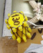
On the fun side, I made my first DIY resistors with a wire thinner than human hair; very difficult. I tried to make shoe-lace-like for lowest capacitance-inductance, but it resulted only so-so: 42 Ohm, because, once you cut it, that's it, you cannot go back. I did not try them yet. I have another thicker wire that I can put in a former to make a honeycomb arrangement. See attachment.
At least for the test phase I mount the power transistors on a
aluminium block which a have from previous projects (w=30mm h=8mm) and screw them via 3pole terminal block to the PCB. This way the power transistors can easily be replaced and the unit PCB-Alu Block can be easily removed from heat sink.
I hope this has no negative effect on sound quality.
The attached drawing can serve as an example as I don't know how you prefer to mount the power transistors to the heat sink.
Thanks very much, dear JOSI1.
That helps a lot.
I will mount them as you show on your "direct mounting on heat-sink" diagram. 😎
Edit: I forgot to mention that the Vbe transistor mounting has a potential problem as it relates only with main BJTs, which see much less power dissipation than the MOSFETs...
Though my VFET bootstrap amp would have other arrangement.

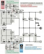
As always, I recommend the "charge-transfer supply" from -ECdesigns-, with upgraded devices for higher power. Any advice on possible improvements for this circuits are welcome. 🙂
Cheers,
M.
Attachments
Last edited:
Hi Max,
You can mount the Vbe transistor anywhere. I connected it to a 20cm 3 pole cable without any effect on stability.
Perhaps you can mount it on small metal sheet contacted to main BJT and MOSFET.
I forgot to mention that the Vbe transistor mounting has a potential problem as it relates only with main BJTs, which see much less power dissipation than the MOSFETs...
You can mount the Vbe transistor anywhere. I connected it to a 20cm 3 pole cable without any effect on stability.
Perhaps you can mount it on small metal sheet contacted to main BJT and MOSFET.
Hi Max,
You can mount the Vbe transistor anywhere. I connected it to a 20cm 3 pole cable without any effect on stability.
Perhaps you can mount it on small metal sheet contacted to main BJT and MOSFET.
True. We'll find a way.
On the other hand, I experimented very stable bias with the (modded) Hagerman Vbe multiplier so maybe this is a non-issue...the Red PCB amp has still simple Vbe multiplier circuit and bias wanders a little.
Remember I praised the JFETinput-MPSA18 VAS as being the cleanest? It can be sort of hard on some CDs. I have not tested it yet on my analog sources...the ALLBJTinput-BD139VAS, while not being so clean on highs, is still very enjoyable, with lots of dynamics and midbass, and is preferred on Rock, Jazz and maybe also on symphonic music...I wish I could have a middle term...maybe Riken Ohm as R50 for the MPSA18VAS... 😀
Cheers,
M.
Max,
Regarding your Charge Transfer supply I have the following:
The idea to isolate the power supply from mains during the charge time is great, it will help to block noise on the mains and stop sharp peaks caused by the rectifiers from entering the power supply
So far so good. But this will only happen with an ideal switch having no feedthrough capacitance.
So select Fets with the lowest output capacitance to diminish this effect.
The other thing is the 2.2Ohm resistor, although good for filtering, seems quite a bit.
With 50 Watt into a 8Ohm speaker, voltage drop would almost be 14 Volt !
Hans
Max,
Regarding your Charge Transfer supply I have the following:
The idea to isolate the power supply from mains during the charge time is great, it will help to block noise on the mains and stop sharp peaks caused by the rectifiers from entering the power supply
So far so good. But this will only happen with an ideal switch having no feedthrough capacitance.
So select Fets with the lowest output capacitance to diminish this effect.
The other thing is the 2.2Ohm resistor, although good for filtering, seems quite a bit.
With 50 Watt into a 8Ohm speaker, voltage drop would almost be 14 Volt !
Hans
Thanks Hans. You are quite right.
This circuit was intended for low power DACs and I upgraded to high power to feed my UCD amps (ClassD= very efficient), then, due to good results I blindly kept using them for my Class AB amps...maybe 0R3-0R68 should be better? Or none at all...
Next time I buy MOSFEts I will have to remember to look for low output capacitance... 🙁
About both versions' listening sessions:
If I was forced to pick one word to define them I would choose "precision" for the JFETinput-MPSA18 VAS and "slam" for the ALLBJT-BD139 VAS. 🙂
I just listened to Brahms' Hungarian dances with the later.
Don't be fooled by the meager power specs...this 35Watter can deliver.
Talking about which, I simulated the Sziklai output with two MOSFETs in parallel per output (just one extra resistor and one extra MOSFET per side) and it seems to work. The output BJT sees little work so I should not fail, but if someone is considering driving it at party levels, this // output could be for him. The other outputs, like the Darlington or the QUAD, may also work but I have not simulated them...
Cheers,
M.
I think you can discard the resistor completely.Thanks Hans. You are quite right.
This circuit was intended for low power DACs and I upgraded to high power to feed my UCD amps (ClassD= very efficient), then, due to good results I blindly kept using them for my Class AB amps...maybe 0R3-0R68 should be better? Or none at all...
Next time I buy MOSFEts I will have to remember to look for low output capacitance... 🙁
About both versions' listening sessions:
If I was forced to pick one word to define them I would choose "precision" for the JFETinput-MPSA18 VAS and "slam" for the ALLBJT-BD139 VAS. 🙂
I just listened to Brahms' Hungarian dances with the later.
Don't be fooled by the meager power specs...this 35Watter can deliver.
Talking about which, I simulated the Sziklai output with two MOSFETs in parallel per output (just one extra resistor and one extra MOSFET per side) and it seems to work. The output BJT sees little work so I should not fail, but if someone is considering driving it at party levels, this // output could be for him. The other outputs, like the Darlington or the QUAD, may also work but I have not simulated them...
Cheers,
M.
The mosfets come in very gentle and switch off the same way, like a variable resistor. No need for extra resistors IMHO.
You are referring to Class D UCD amps. I'm curious to hear what your opinion is in compare to your Amnesis, mainly because you are a classical music listener like myself.
Hans
I think you can discard the resistor completely.
The mosfets come in very gentle and switch off the same way, like a variable resistor. No need for extra resistors IMHO.
You are referring to Class D UCD amps. I'm curious to hear what your opinion is in compare to your Amnesis, mainly because you are a classical music listener like myself.
Hans
Dear Hans,
Best advice of 2019. 😀
I already began modifying circuits to good effect. On some I am trying lower (0R47 to 0R68) resistance; those in which noise is very critical...aren't they all?
This is the beauty of our beloved forum: the communion of illiterate fanatics, like yours truly, that are willing to try every crazy hypothesis out there, with real experts whom, lets say, are quite more selective on their projects 😀 but who are nevertheless willing to help their little brothers in trouble!
There are big problems like the last one that totally escapes us, even with ample evidence of trouble, which you pick instantly as a matter of basics of the trade.
UCD amps: mine were modified a good extent to give better chance of success. I even toasted one or two in the attempt...they have evident pros: very user friendly; very reliable; low consumption; they absolutely don't care with which load you pair them and deliver consistent sound. The cons, and they are big IMHO, are mainly a lack of slam and punch on the mid-bass and bass, and a lack of "suspension of disbelief" effect, attributes which, I am not sure if I mentioned them previously 😀 are very OK with the Amnesis...UCD sound too artificial to me, a little "two dimensional"...Bruno is a genius, no doubt about it, but, as probably you already suspect, and being myself born with Aquarius ascending 😀 I am in the quest for the missing aspects of the theory that makes Solid State sound uninvolving.
So far I have learned that "LTMD" strategies and "boostrapping everything you can" work for me, for my subjective listening pleasure and satisfaction.
Can this be bettered? I hope so! But it will need a little help from my friends...
Cheers,
M.
Last edited:
Dear Max,Dear Hans,
Best advice of 2019. 😀
I already began modifying circuits to good effect. On some I am trying lower (0R47 to 0R68) resistance; those in which noise is very critical...aren't they all?
This is the beauty of our beloved forum: the communion of illiterate fanatics, like yours truly, that are willing to try every crazy hypothesis out there, with real experts whom, lets say, are quite more selective on their projects 😀 but who are nevertheless willing to help their little brothers in trouble!
There are big problems like the last one that totally escapes us, even with ample evidence of trouble, which you pick instantly as a matter of basics of the trade.
UCD amps: mine were modified a good extent to give better chance of success. I even toasted one or two in the attempt...they have evident pros: very user friendly; very reliable; low consumption; they absolutely don't care with which load you pair them and deliver consistent sound. The cons, and they are big IMHO, are mainly a lack of slam and punch on the mid-bass and bass, and a lack of "suspension of disbelief" effect, attributes which, I am not sure if I mentioned them previously 😀 are very OK with the Amnesis...UCD sound too artificial to me, a little "two dimensional"...Bruno is a genius, no doubt about it, but, as probably you already suspect, and being myself born with Aquarius ascending 😀 I am in the quest for the missing aspects of the theory that makes Solid State sound uninvolving.
So far I have learned that "LTMD" strategies and "boostrapping everything you can" work for me, for my subjective listening pleasure and satisfaction.
Can this be bettered? I hope so! But it will need a little help from my friends...
Cheers,
M.
Thanks for your Class D observation.
I had the same experience, it sounded like a computer without getting involved into the music. No emotion just clean sound.
That’s why I’m still addicted to class A (and LP’s) .
Hans
Last edited:
Dear Max,
Thanks for your Class D observation.
I had the same experience, it sounded like a computer without getting involved into the music. No emotion just clean sound.
That’s why I’m still addicted to class A (and LP’s) .
Hans
You need an Amnesis, then 😀
I have also some Class A amps (my first serious amp was a Monarchy Audio SE100 deluxe) but I struggle with the idea of power consumption, especially on summer,,,I am talking about normal summers not like this last one where we had one day 36°C and the rest were intermitently cold due to clouds. For example, today 17°C max. is expected, cloudy with a little rain...coldest summer I can remember.
My main class A is a Tokin SK180 single ended 8 Watter but with added LTMD differential input section. 😎 Totally improved sound. I have posted here the diagram.
I also listen from time to time to my analog sources (I forgot to test the Amnesis with them) but there is some extra work involved with them that, we, spoiled digital era people, detest...
My little experience with TT: I made an unipivot arm with an old violin bow which sounds quite good. I posted it here under "man on wire" unipivot tonearm. 😎 Almost free...
I am sure that my new machine-man can optimize it. Bronze and Pernambuco wood.
Then I bought an old Otari MKII5050 R2R machine for USD$230 (total, including postage) that is now very modified so that its sound is decent. This format is potentially the best but has a lot of cons, like scarcity of recordings, high price of them, several different types of tapes and equalization and biasing. Dynamics though are the best out there. No compression from the old recording engineers...I spent a lot of time modifying the reproducing amplifier, which is the critical part. When I'll find a better candidate I will totally replace it. Talking about which, I figured it out that maybe we can create a high gain preamplifier, for both, tape and vinyl, with LTMD principles, derived form Amnesis. I tried once but THD was horrible...maybe I can modify an existing one.
It's funny how, for me, vinyl sounds "solid" and tape sounds "soft". 🙂
I forgot to comment that one of the main reasons why I no longer crave for analog is that now I have -ECdesigns-'s MOSAIC UV DAC. 😎
 He is located in Netherlands and apparently he is now launching his new system, with very good prices, I must say, much lower than before. If I were you, I would pay him a visit but I am on the other side of the planet.
 ECdesigns
Cheers,
M.
Last edited:
It’s almost hilarious, that you know a company in the Netherlands that I’ve never heard of and I’m certainly not the only one.You need an Amnesis, then 😀
I have also some Class A amps (my first serious amp was a Monarchy Audio SE100 deluxe) but I struggle with the idea of power consumption, especially on summer,,,I am talking about normal summers not like this last one where we had one day 36°C and the rest were intermitently cold due to clouds. For example, today 17°C max. is expected, cloudy with a little rain...coldest summer I can remember.
My main class A is a Tokin SK180 single ended 8 Watter but with added LTMD differential input section. 😎 Totally improved sound. I have posted here the diagram.
I also listen from time to time to my analog sources (I forgot to test the Amnesis with them) but there is some extra work involved with them that, we, spoiled digital era people, detest...
My little experience with TT: I made an unipivot arm with an old violin bow which sounds quite good. I posted it here under "man on wire" unipivot tonearm. 😎 Almost free...
I am sure that my new machine-man can optimize it. Bronze and Pernambuco wood.
Then I bought an old Otari MKII5050 R2R machine for USD$230 (total, including postage) that is now very modified so that its sound is decent. This format is potentially the best but has a lot of cons, like scarcity of recordings, high price of them, several different types of tapes and equalization and biasing. Dynamics though are the best out there. No compression from the old recording engineers...I spent a lot of time modifying the reproducing amplifier, which is the critical part. When I'll find a better candidate I will totally replace it. Talking about which, I figured it out that maybe we can create a high gain preamplifier, for both, tape and vinyl, with LTMD principles, derived form Amnesis. I tried once but THD was horrible...maybe I can modify an existing one.
It's funny how, for me, vinyl sounds "solid" and tape sounds "soft". 🙂
I forgot to comment that one of the main reasons why I no longer crave for analog is that now I have -ECdesigns-'s MOSAIC UV DAC. 😎
ECdesigns
Cheers,
M.
However, as I found out, your DAC is still a NOSDAC, but they fell off their belief and now produce “regular” multi bit DAC’s from standard components, that’s why they are so much cheaper.
My class A amp consumes 500Watt per channel while playing, but switches back to 50Watt when nothiing is happening. 😀
It’s almost hilarious, that you know a company in the Netherlands that I’ve never heard of and I’m certainly not the only one. Maybe because you do not follow the "Ultimate NOS DAC with TDA1451A DAC" thread...
However, as I found out, your DAC is still a NOSDAC, but they fell off their belief and now produce “regular” multi bit DAC’s from standard components, that’s why they are so much cheaper.
From what I understand it is not a "regular" multibit DAC. Apart, It uses (or used) ternary logic 😎 with DC coupled output. Well, John Brown can explain much better than I possibly can. And being "discrete" does not make it cheaper to build...compared to a chip that is.
My class A amp consumes 500Watt per channel while playing, but switches back to 50Watt when nothiing is happening. 😀
Model?
Well, the MOSAIC has the least "digital sound" of all the sources I have tried and it sounds like music to me. 🙂
Cheers,
M.
Interesting to know, I never auditioned a NOS DAC, simply because there aren’t that many. And the ones on the market weren’t very well tested by stereophile because of cheap internal realisation.Well, the MOSAIC has the least "digital sound" of all the sources I have tried and it sounds like music to me. 🙂
Cheers,
M.
But it doesn’t mean that they cannot be very good with a better design.
However, your ears may have ultra sonic filters, your amp has not an will have to amplify all the many spectra at x*Fs without getting oversteered.
That makes that your amp should really shine in the higher FR as well, which applies to the Amnesis when slew rate is high enough.
Hans
Interesting to know, I never auditioned a NOS DAC, simply because there aren’t that many. And the ones on the market weren’t very well tested by stereophile because of cheap internal realisation.
But it doesn’t mean that they cannot be very good with a better design.
However, your ears may have ultra sonic filters, your amp has not an will have to amplify all the many spectra at x*Fs without getting oversteered.
That makes that your amp should really shine in the higher FR as well, which applies to the Amnesis when slew rate is high enough.
Hans
Now listening to the JFETinput-MPSA18 VAS with an AK4393 based DAC with discrete LTMD differential amplifier output: it sounds as if there was a magnifying glass 😱
Edit: he doesn't forgive bad recordings though...
The "Ultimate NOS DAC..." thread was inaugurated 12th May 2006, 04:07 PM! John went through several iterations until he gave up on the TDA1541 chip and decided to create his own converter. I could quote him but I prefer not to send unrequested info 😀 You should give it a try. Look, now that you mention "reviews" I did a quick search and found one review from a former version (previous to mine) of the DAC (the guy is an extreme perfectionist), and several conversation on different fora:
EC Designs Mosaic T DAC | HFA - The Independent Source for Audio Equipment Reviews
I'll stop propaganda now.
Cheers,
M.
Last edited:
- Home
- Amplifiers
- Solid State
- The AMNESIS amp: a good amplifier, like a gentleman, has no memory.