Question, do you have the snubber components across the drain and gate local to the Mosfets? (Not on the main board)
Snubbers are local on the breakout boards. A quick test shows that they are still intact.
Sorry about your incident. The fact that it worked for months without issue and breaks at power on seems to indicate as you suggest, a short. Are you at least using CL-60’s or other NTCs on the trafo primary as a soft start?
Are your heat sink blocks grounded to protective earth?
Sometimes capacitance can be set up between the heatsink active and that can cause oscillation. The hum sound was the trafo vibrating due to the short. You may have a burr or some sharp point pike through the silicone insulator. Or are you using ceramic spacer pads?
Test the SLB part by itself with a new BJT. Disconnect the 0.1R to isolate the PSU. If that works, test with new MOSFET in place. Use an NTC this time in the primary trafo.
Have a DVM connected across the source resistor of the amp. Watch closely and when you flip power on, if more than 5A flows for more than 1 second switch it off and debug.
And now my shameful responses 🙂
No, I wasn't, though I think my APC does some amount of soft start (or at least has a slow blow circuit breaker / overload protection).
They weren't in my testing setup, I'll make sure to add that before I run it again. I had already planned for it on during my final build out.
I'm using a Silpad insulating sheet, planning on Berquist Red for the final build. Very possible either the sheet shifted or got punctured. I'll have to check it out more thoroughly and will likely come up with a better mounting strategy.
Which 0.1R is that? I'm guessing not the one thats part of the CRC?
I'll plan on testing out the cap-mx / PSU with a slow ramp up on my variac and then move to testing the MOSFET with a CL-60 or soft start in place. I'm pretty sure I already have one in my parts drawer...
Thanks for all the help. Hopefully I can report back with some good news and lay out some gotchas / lessons for future builders 🙂
Greg
Are you at least using CL-60’s or other NTCs on the trafo primary as a soft start?
No, I wasn't, though I think my APC does some amount of soft start (or at least has a slow blow circuit breaker / overload protection).
Are your heat sink blocks grounded to protective earth?
They weren't in my testing setup, I'll make sure to add that before I run it again. I had already planned for it on during my final build out.
You may have a burr or some sharp point pike through the silicone insulator. Or are you using ceramic spacer pads?
I'm using a Silpad insulating sheet, planning on Berquist Red for the final build. Very possible either the sheet shifted or got punctured. I'll have to check it out more thoroughly and will likely come up with a better mounting strategy.
Test the SLB part by itself with a new BJT. Disconnect the 0.1R to isolate the PSU. If that works, test with new MOSFET in place. Use an NTC this time in the primary trafo.
Which 0.1R is that? I'm guessing not the one thats part of the CRC?
I'll plan on testing out the cap-mx / PSU with a slow ramp up on my variac and then move to testing the MOSFET with a CL-60 or soft start in place. I'm pretty sure I already have one in my parts drawer...
Thanks for all the help. Hopefully I can report back with some good news and lay out some gotchas / lessons for future builders 🙂
Greg
I need a bit of assistance from the experts.
Took my time on this ABBB build. Built the V- and V+ cap mx first and tested them using light bulb inline and finally plugged straight to wall. All good, no magic smoke and was reading around 47v. Antek 32vac secondaries.
Finished the build on each amp and used the inline bulb again with no bad results, so plugged directly into wall. No sound. This is true of both amp boards.
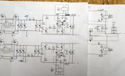
I removed R203 and R223, measured about 49vdc on both positive and negative legs. Reinstalled them and measured +12v and -44.9v on the respective outputs.
I have written the voltages on the schematics. I am guessing I have an issue on the plus Cap Mx side. Gone over the board, checked solder connections, etc.
Thoughts appreciated.
Tnx
David
Took my time on this ABBB build. Built the V- and V+ cap mx first and tested them using light bulb inline and finally plugged straight to wall. All good, no magic smoke and was reading around 47v. Antek 32vac secondaries.
Finished the build on each amp and used the inline bulb again with no bad results, so plugged directly into wall. No sound. This is true of both amp boards.
I removed R203 and R223, measured about 49vdc on both positive and negative legs. Reinstalled them and measured +12v and -44.9v on the respective outputs.
I have written the voltages on the schematics. I am guessing I have an issue on the plus Cap Mx side. Gone over the board, checked solder connections, etc.
Thoughts appreciated.
Tnx
David
Attachments
All I can say is the check your flying lead wires to make sure that they are correct pin out. Also do you have PNP for output on +ve rail and NPN on -ve rail. Check to make sure you have NPN as the master BJT (BD139) for +ve rail and PNP (BD140) as master -ve rail.
Hi David,
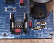
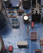
Can you post a few detailed pics of your ABBB board and setup?
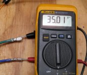
The voltage seems a bit high from a 32vac secondary.
Can you post a few detailed pics of your ABBB board and setup?
The voltage seems a bit high from a 32vac secondary.
Here are several shots. I am reading 35vac on each secondary (TVA volts!). R203 and R223 are still out in these photos.
I haven't tried X's suggestion. I believe I may have mild dyslexia, so miss wiring a connector is definitely a possibility.
Thanks Vunce
I haven't tried X's suggestion. I believe I may have mild dyslexia, so miss wiring a connector is definitely a possibility.
Thanks Vunce
Attachments


Yeah, double check all BJT and Mosfet flying lead pinouts for correctness. You can power up with capMx BJT’s connected, but not the Mosfets to check voltages. (When the Mosfets are connected, the BJT’s must also be)
Hi Vunce or other builders,
Not sure if this has been asked: Does the aluminum L channel used to pressure the transistors get quite warm.? Does it act to also to get heat away from the transistor case.?
Regards,
Myles
Not sure if this has been asked: Does the aluminum L channel used to pressure the transistors get quite warm.? Does it act to also to get heat away from the transistor case.?
Regards,
Myles
It does indeed get warm/hot and I use it as a way to measure the temp of the MOSFET body. I put a piece of Kapton tape on the channel so that the IR thermometer can get a more accurate reading. Mine is about 67C to 70C. The CPU cooler heatsink fins are about 50C to 55C. Some heat is conducted out of the L channel (a few watts) the bulk of the heat is via the CPU cooler though.
Thanks for info X. I have some plates of copper 7" L x 2" W x 0.25" thick. Just wondering if I can put them to use in getting heat away from the transistor case.
Regards
Regards
Test the SLB part by itself with a new BJT. Disconnect the 0.1R to isolate the PSU. If that works, test with new MOSFET in place. Use an NTC this time in the primary trafo.
X, can you clarify what 0.1R I should disconnect to test just the PSU? It's not immediately obvious to me from the schematic.
Thanks,
Greg
Sorry for giving you wrong info. The 0.1R would simply disconnect main CRC from cap Mx. The way to test SLB without loading it is to disconnect the Molex quick connects from the two MOSFETs.
X, thanks for the clarification! I'm hoping to find some time to test things out this week and see what's going on.
I'm currently using a Bedini 25.25 (25 W x2) to drive a pair of stacked Quads (57s) and they sound awesome. Admittedly the Bedini runs at about 65°C but it has small sinks. This amp should not have a problem. My only concern is the protection circuit, some have had problems with ESLs I believe (hearsay)I'm thinking of using this amp to drive a pair of ESL57s, but would the 57s low impedance at high frequencies (~2R) cause problems at all?
Kevin
@Chiily:
2ohms at what frequencies? That is pretty low and depending on how much current is needed, may cause problems. Do you have a link to the impedance sweep as function of frequency for the ESL's?
2ohms at what frequencies? That is pretty low and depending on how much current is needed, may cause problems. Do you have a link to the impedance sweep as function of frequency for the ESL's?
Hi X,
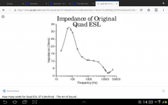
Quad ESL (57) impedance curve attached. The Quads (TMK) can take a maximum voltage swing of 32 V peak-to-peak and then you will get panel arcing. Stokessd here on diyAudio has clamp boards that can be easily installed to protect the tweeter/mid panels. Quad ESL57 clamp board?
A question as regards this amp - is it possible to use a total of four power FETs instead of two to spread the heat load? (please note I am not an electronics expert)
Attachments
Last edited:
I have a pair of Antek AS-4225 transformers that I had been planning to use for a chip amp, but this amp looks very intriguing. I realize using these transformers would reduce max power, but would this amp otherwise perform well at the lower voltage?
My chassis has 330x140x50 heatsinks on each side. Think this would be adequate for the reduced power implementation?
Thanks,
Jay
My chassis has 330x140x50 heatsinks on each side. Think this would be adequate for the reduced power implementation?
Thanks,
Jay
Yes, you would be somewhere near 40w, which isn't all that bad. It would be similar to the Alpha Nirvana in capability. Should work fine.
- Home
- Group Buys
- The Alpha Big Boy with Buttah (ABBB) 52w Class A Amp GB