That’s great news then, the 5U can handle the ABBB then at 500mm. That’s half a meter or 19 in deep case.
Well, it is the first day of February, and I am getting spring fever - which means it is getting close to time to build my ABBB.
Still have some other projects to wrap up.
Been hard these last few months with almost $400.00 worth of parts sitting in an un-opened Mouser box.
I'm still on the fence about cooling. I have a few ideas I am kicking around - I really want something that is both affordable and attractive.
I do have one question though about transformers.
Antek does not make a 500VA 2x32VAC transformer. They do have them in 400VA and in 600VA. 400VA seems a tad borderline to me.
Any thoughts on this would be appreciated.
Thanks,
-Josh
Josh,
For what it’s worth, I went with the AN-6432 - 600VA 32V and all is fine. I figured more pounds of transformer never hurt anyone. I do however wish Antek’s higher VA transformers had an option of a static shield like their smaller ones, I think they stop offering the AS option at 400va.
Greg
For what it’s worth, I went with the AN-6432 - 600VA 32V and all is fine. I figured more pounds of transformer never hurt anyone. I do however wish Antek’s higher VA transformers had an option of a static shield like their smaller ones, I think they stop offering the AS option at 400va.
Greg
Question for those that have gone before building the ABBB.
I am building two mono blocks with Antek 600va transformers. I would like to keep the size down as much as possible. This will be a closed cabinet/case with venting.
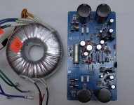
So in terms of mounting the toroid, and I know it does generate a magnetic field, what position would be best or it really doesn't matter. A, horizontal mounting, B, vertical perpendicular mount, or C vertical parallel mount.
The cpu cooling blocks will be to the right of the amp board.
Tnx
David
I am building two mono blocks with Antek 600va transformers. I would like to keep the size down as much as possible. This will be a closed cabinet/case with venting.
So in terms of mounting the toroid, and I know it does generate a magnetic field, what position would be best or it really doesn't matter. A, horizontal mounting, B, vertical perpendicular mount, or C vertical parallel mount.
The cpu cooling blocks will be to the right of the amp board.
Tnx
David
Attachments

@drpo
keep in mind the magnetic flux on a toroidal transformer is also toroidal. The magnetic flux "travels" up the center (where the bolt goes) and around the body and back to the center.
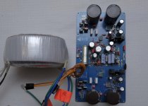
This means that pic 1 and pic 3 are functionally the same. In both cases the flux will pass vertically through the coupling cap. In pic 2, the flux will pass through the coupling cap horizontally.
Mounting height does matter as well.
If these are your only options, pic 3 is probably best since the mounting plate will provide some "taming" of the flux. better would be to mount as in pic 2, and move the transformer up or down so the flux lines are farther from the signal path. The flux will have much less affect on SQ if it is near the rectifier than near the signal path.
Better yet would be an iron or steel sheet that spans the entire length of the PCB between it and the transformer. Maybe pony up for a metal can and use as in pic 3 (the cans from Antek are expensive). Magnetic flux behaves in unexpected ways, and shields need to pretty much enclose the transformer, or span well beyond the diameter (with no hole) to be effective.
IMO the proposed mounting positions are all too close to the signal path to be used with out shielding. You have a lot invested in this, this is not (imo) a good place to save a few bucks by skipping a metal plate or can.
keep in mind the magnetic flux on a toroidal transformer is also toroidal. The magnetic flux "travels" up the center (where the bolt goes) and around the body and back to the center.
This means that pic 1 and pic 3 are functionally the same. In both cases the flux will pass vertically through the coupling cap. In pic 2, the flux will pass through the coupling cap horizontally.
Mounting height does matter as well.
If these are your only options, pic 3 is probably best since the mounting plate will provide some "taming" of the flux. better would be to mount as in pic 2, and move the transformer up or down so the flux lines are farther from the signal path. The flux will have much less affect on SQ if it is near the rectifier than near the signal path.
Better yet would be an iron or steel sheet that spans the entire length of the PCB between it and the transformer. Maybe pony up for a metal can and use as in pic 3 (the cans from Antek are expensive). Magnetic flux behaves in unexpected ways, and shields need to pretty much enclose the transformer, or span well beyond the diameter (with no hole) to be effective.
IMO the proposed mounting positions are all too close to the signal path to be used with out shielding. You have a lot invested in this, this is not (imo) a good place to save a few bucks by skipping a metal plate or can.
Another layout question. Not sure how much heat the BJT on the power supply generate. Will the Dell heatsink turned on its side like in the photo be able to dissipate the heat?
My goal is to try and keep the overall size of each mono block reasonably small and position the toroid away from the amp board.
Open to suggestions.
Tnx
David
My goal is to try and keep the overall size of each mono block reasonably small and position the toroid away from the amp board.
Open to suggestions.
Tnx
David
Attachments
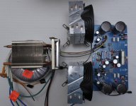
You could put the BJT and MOSFET on each side on a common Dell CPU cooler if you have the wide copper pad version. It can handle it easily. I do the same on one of my amps where the Dell removes 160w total.
The BJT dissipates the current x voltage drop. So 3A x 3v is 9w ea. Your main MOSFET is 37v x 3A or 111w. Plus 9w is 120w total. No need for third CPU cooler.
The BJT dissipates the current x voltage drop. So 3A x 3v is 9w ea. Your main MOSFET is 37v x 3A or 111w. Plus 9w is 120w total. No need for third CPU cooler.
Super X. I am using the DedoCool sinks I bought for the original ABB, which I believe will handle the 120w or so.
@drpro,
Could you please post the dimension of that Deepcool thermal pad. Thanks for the help.
Myles
Could you please post the dimension of that Deepcool thermal pad. Thanks for the help.
Myles
Thanks drpro,.
One thing I am looking at is the direct contact heat pipes, which is where the heat pipes contact each other across the thermal pad. Not sure if this is marketing hype or whether it does aid in better heat dissipation. I think this technique is used by Coolmaster and Arctic.
The Coolmaster cooler I was looking at has a 4 pipe thermal pad area of 37mm x 56mm, so it should be good for 2 transistors.
MM
I wouldn’t worry about direct contact heatpipes, although the one Drpro is using seems to have that feature. The Dell FD ones I use have a massive copper block that collects the heat pretty well. I think the Dell is 75mm wide.
Build update
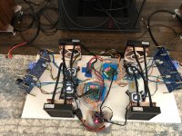
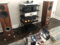
So I have some good news and bad news about my ABBB build. First, the good news, I have had my build up and running on my main system for about the past month or month and a half. It is a bit of a precarious setup, see picture, (no kids or dogs allowed in the room while I'm listening 🙂), but I've really enjoyed it across all of my music. It has plenty of umph and the tight bass is really something special.
The fan noise is really nothing of note, the pump is a bit louder than the fan, but once I isolated the pump / transistor mounting bar with some rubber feet, it was nearly silent as well. I think with a proper case enclosing the pumps, it'll run silent enough for my needs in my small listening room.
Now the bad news. A few days ago (of course when I was demoing my harebrained project for an in-law), I lost a channel 😡 I had been using the amp daily in its WIP state without issues. However, this time I turned on power, about 3-5 seconds I notice the loud humming, I think from a traffo, and my APC power strip kicks off for over current (thank goodness). I smell a bit of smoke, but nothing room filling. Some observations of the damage:
- Only one channel affected, yay!
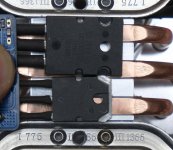
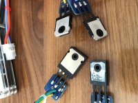
- All remote transistors (BJT, Mosfets) are goners. N-Mos has the most noticeable damage. All tested on an Atlas DCA75 and show shorts.
- No observable damage to the ABBB PCB or components on it. Initial sniff test had a bit of a smell to it, but I can't visually observe any damage to the board or its components.
My best bet of what happens is that my mounting of one of the transistors slipped past the thermal pad and shorted against the water block. One one of the water blocks has some burn marks, I think where the N-Mos was mounted. I also have been testing it without any soft start implemented, so there will be some current inrush on startup, but hasn't tripped my power strip, etc in my month plus of use.
My question is, are there any components I need to take off the PCB and test before plugging in the remaining transistors and testing the affected channel? Any other ideas about what else could have gone wrong?
Unfortunately, I'm moving the ABBB back down to the lab. However, I needed to do that anyway as I start making progress on the chassis and design a better transistor mounting plans 😀 I'm also thinking about designing some thermal / fan management board and soft start circuit.
Thanks for any help!
Greg
So I have some good news and bad news about my ABBB build. First, the good news, I have had my build up and running on my main system for about the past month or month and a half. It is a bit of a precarious setup, see picture, (no kids or dogs allowed in the room while I'm listening 🙂), but I've really enjoyed it across all of my music. It has plenty of umph and the tight bass is really something special.
The fan noise is really nothing of note, the pump is a bit louder than the fan, but once I isolated the pump / transistor mounting bar with some rubber feet, it was nearly silent as well. I think with a proper case enclosing the pumps, it'll run silent enough for my needs in my small listening room.
Now the bad news. A few days ago (of course when I was demoing my harebrained project for an in-law), I lost a channel 😡 I had been using the amp daily in its WIP state without issues. However, this time I turned on power, about 3-5 seconds I notice the loud humming, I think from a traffo, and my APC power strip kicks off for over current (thank goodness). I smell a bit of smoke, but nothing room filling. Some observations of the damage:
- Only one channel affected, yay!
- All remote transistors (BJT, Mosfets) are goners. N-Mos has the most noticeable damage. All tested on an Atlas DCA75 and show shorts.
- No observable damage to the ABBB PCB or components on it. Initial sniff test had a bit of a smell to it, but I can't visually observe any damage to the board or its components.
My best bet of what happens is that my mounting of one of the transistors slipped past the thermal pad and shorted against the water block. One one of the water blocks has some burn marks, I think where the N-Mos was mounted. I also have been testing it without any soft start implemented, so there will be some current inrush on startup, but hasn't tripped my power strip, etc in my month plus of use.
My question is, are there any components I need to take off the PCB and test before plugging in the remaining transistors and testing the affected channel? Any other ideas about what else could have gone wrong?
Unfortunately, I'm moving the ABBB back down to the lab. However, I needed to do that anyway as I start making progress on the chassis and design a better transistor mounting plans 😀 I'm also thinking about designing some thermal / fan management board and soft start circuit.
Thanks for any help!
Greg
Attachments
- Home
- Group Buys
- The Alpha Big Boy with Buttah (ABBB) 52w Class A Amp GB