Hi Josh,
Your diagram shows one of the primaries connected to earth ground. I assume that’s a typo. You should add an NTC (CL60 or 8D-20) in series with the line from the wall plug to the primaries. That will serve to be soft start and help reduce hum. Also, don’t twist the earth ground with the mains L and N lines. They will induce hum into the ground line.
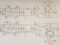
Here is my sketch. I think you are already twisting the AC secondary wires?
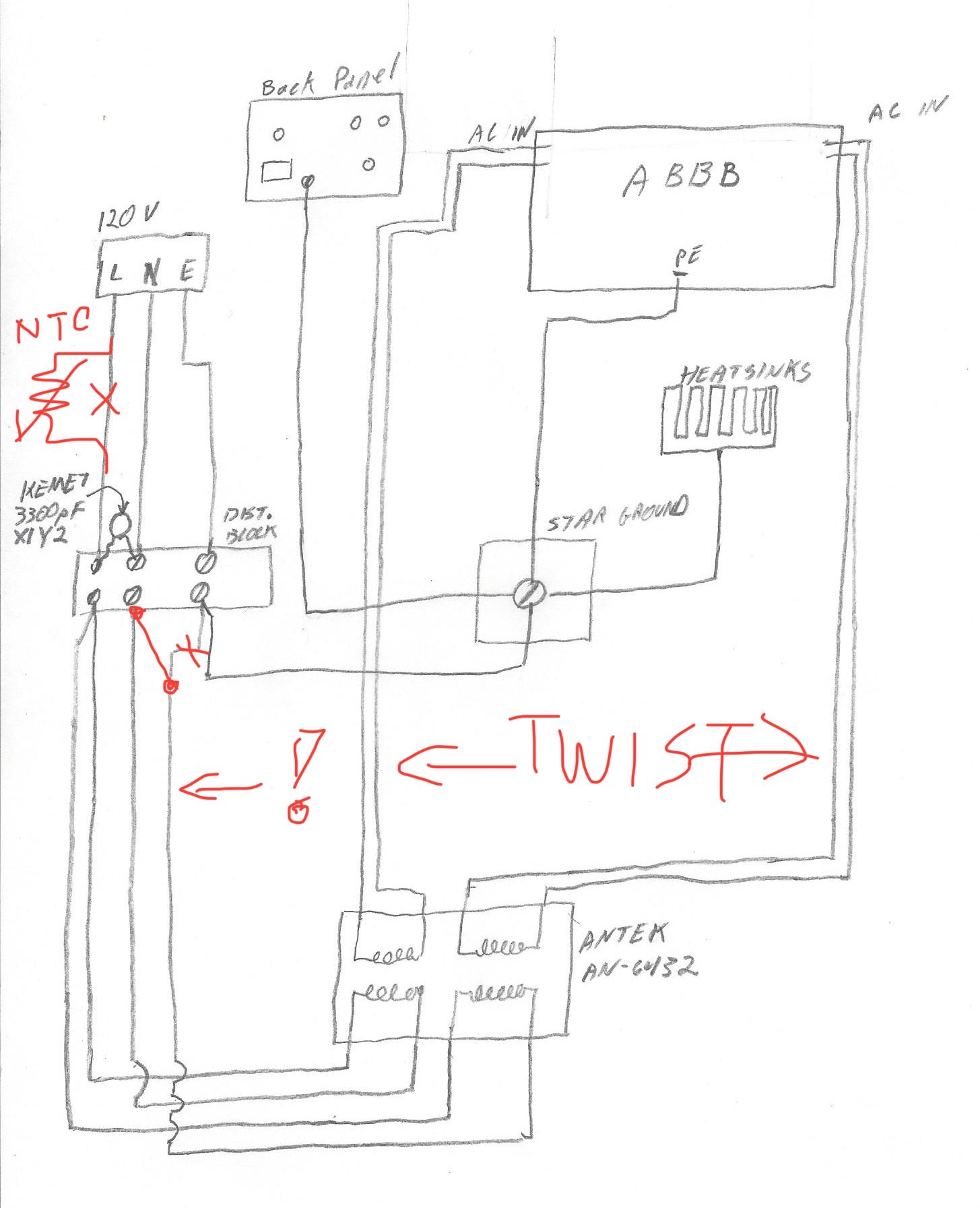
Your diagram shows one of the primaries connected to earth ground. I assume that’s a typo. You should add an NTC (CL60 or 8D-20) in series with the line from the wall plug to the primaries. That will serve to be soft start and help reduce hum. Also, don’t twist the earth ground with the mains L and N lines. They will induce hum into the ground line.
Here is my sketch. I think you are already twisting the AC secondary wires?
Attachments
Thanks for the really fast answer.
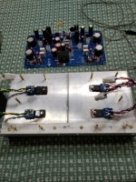
I went ahead and unwound the earth from the mains, and added a CL-60 along the load line.
Sadly, it didn't help.
My mains power is pretty decent, so I am not too surprised. Winding the earth didn't affect my M2x, but I also use a mains filter on that and good wire. So who knows really...
Attached is a pic of the new set up.
Once again, I can't thank you enough for your help.
It is greatly appreciated.
Thanks,
-Josh
Your are correct 🙁I assume that’s a typo.
Yes, you are correct again 🙂I think you are already twisting the AC secondary wires?
I went ahead and unwound the earth from the mains, and added a CL-60 along the load line.
Sadly, it didn't help.
My mains power is pretty decent, so I am not too surprised. Winding the earth didn't affect my M2x, but I also use a mains filter on that and good wire. So who knows really...
Attached is a pic of the new set up.
Once again, I can't thank you enough for your help.
It is greatly appreciated.
Thanks,
-Josh
Attachments
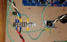
You get no hum when playing from say your phone right? But hum when connected to the DAC that’s connected to the mains. This is a common problem. You may have a ground loop from your source - the shield wire on your RCA cable is the ground loop. Can you add to the diagram how the DAC/source is grounded and what it’s power supply is?
What is that diode bridge doing there with thick black and white wire?
What is that diode bridge doing there with thick black and white wire?
Last edited:
You get no hum when playing from say your phone right? But hum when connected to the DAC that’s connected to the mains. This is a common problem. You may have a ground loop from your source - the shield wire on your RCA cable is the ground loop. Can you add to the diagram how the DAC/source is grounded and what it’s power supply is?
What is that diode bridge doing there with thick black and white wire?
One question leads to another, as they say. I am working on a proper answer, and a conditional matrix. I need to track a few things down first.
I will have your info this weekend.
Thanks,
-Josh
You get no hum when playing from say your phone right? But hum when connected to the DAC that’s connected to the mains. This is a common problem. You may have a ground loop from your source - the shield wire on your RCA cable is the ground loop. Can you add to the diagram how the DAC/source is grounded and what it’s power supply is?
What is that diode bridge doing there with thick black and white wire?
The diode bridge is for the 12V supply to the fan controller.
I want to thank you all for your help and patience.
To add to everything else, my mother had a minor stroke (she is fine), and a power surge seems to have killed my JVC RS25U projector 🙁
After spending much time trying different things, and building a conditional table, I found the problem.
During my efforts to maximally mis-handle everything, I damaged one of the traces on the board. I repaired the trace, and the amp is now essentially hum free.
I was able to listen to it for about 45 minutes the other night, and so far it seems very nice. If I had to use a single word to describe it, it would be "authority." The amp as authority.
OK, to move onto less interesting questions:
One of the amps runs much hotter than the other.
62C and 59C vs 57C and 54C
I monitor temps with thermistors attached to the heatsink copper die.
I run the fans at full speed, and do not use PWM.
Should I worry much about this? I expect the thermal paste also needs to cycle a few times before I get optimal contact.
I have a second question as well.
Is there any reason not to put a relay between the transformer and the board?
I'd like to have an auto-shutdown feature incase the amp overheats. I currently have a 120dB siren hooked up that will scream when the temp exceeds 95C.
Thanks again,
-Josh
Hi Josh,
Sorry to hear about your mother - hope she recovers quickly!
Congrats on finding the problem! Glad that the amp sounds nice - autority of a 50w Class A is something I have noticed too vs a 100w Class AB.
The temps sound Ok - some differences result from different heatsink contact pressure and amount of thermal paste. Check your bias currents and if they are all identical, then should be similar temps. I have also seen 5 deg variations for temps on mine. Increasing the clamp bolt pressure can decrease the temps. etc.
No reason not to have a relay but make sure it can handle high currents. Good idea to connect it to a safety shutoff. You can also use those coffee pot thermal switches that disconnect when greater than some set temp lie 85C etc. But they reset so you would get recycling unless you use it to activate a latch.
Happy Xmas and enjoy your amp!
Hi XRK,
I have two 400VA transformers, they only have single 25VAC outputs. Is ABBB ok to use with two transformers, rather than one with dual secondaries?
Thanks
I have two 400VA transformers, they only have single 25VAC outputs. Is ABBB ok to use with two transformers, rather than one with dual secondaries?
Thanks
Nope. You need 2 transformers, each with dual secondaries. Yours are also too low in secondary voltage. Per the first post:Hi XRK,
I have two 400VA transformers, they only have single 25VAC outputs. Is ABBB ok to use with two transformers, rather than one with dual secondaries?
Thanks
“
400VA to 500VA 32v power transformer (per channel) with dual secondaries is recommend to achiev about +/-37v rails”

Doh, silly me, of course it is, one ABBB per channel. I think I’d better get some rest 🙂Nope. You need 2 transformers, each with dual secondaries. Yours are also too low in secondary voltage. Per the first post:
“
400VA to 500VA 32v power transformer (per channel) with dual secondaries is recommend to achiev about +/-37v rails”
Hi All,
Whelp Id tried to be as thorough and careful as possible in my assembly of a 4 channel amp with these modules but after bench testing with a water cooling setup that I'd abandoned and moving towards a passive/active air cooled setup id managed to cross my bjt and mosfet connections and managed to cause some destruction when I went from my 100watt to 300watt light bulb for power testing.
Id assembled the modules upside down, I think, and crossed the following,
x231 with x111
x144 with x211
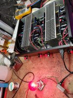
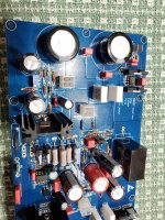
On two boards r234 smoked, but still measure at 68 ohms. And on the other two a trace between c224 / c226 and v221 / v223 got extremely hot and discolored/smoked. I threw the ohm meter on the bjt's and output mosfets and at least from what I can measure they seem ok, not shorted to the heatsinks as well. At this point, after correcting the mostfet and bjt connections all 4 modules have +30/-44 on the output of the power supply stages, and go into protect. There seems to be no activity on the boards (only around 10watts of idle draw even with the output mosfets plugged in). I've attached some pics for reference. Any leads on where/what I might check next?
Whelp Id tried to be as thorough and careful as possible in my assembly of a 4 channel amp with these modules but after bench testing with a water cooling setup that I'd abandoned and moving towards a passive/active air cooled setup id managed to cross my bjt and mosfet connections and managed to cause some destruction when I went from my 100watt to 300watt light bulb for power testing.
Id assembled the modules upside down, I think, and crossed the following,
x231 with x111
x144 with x211
On two boards r234 smoked, but still measure at 68 ohms. And on the other two a trace between c224 / c226 and v221 / v223 got extremely hot and discolored/smoked. I threw the ohm meter on the bjt's and output mosfets and at least from what I can measure they seem ok, not shorted to the heatsinks as well. At this point, after correcting the mostfet and bjt connections all 4 modules have +30/-44 on the output of the power supply stages, and go into protect. There seems to be no activity on the boards (only around 10watts of idle draw even with the output mosfets plugged in). I've attached some pics for reference. Any leads on where/what I might check next?
Attachments
In general, R215 and R235 are the ones that burn if you have a bad connection between the off-board BJTs and the main PCB.
When you say you crossed x231 and x111 and X144 and x211, does that mean you swapped them by accident? That would be bad as the BJTs would act as dead shorts and it would act like a wire and max current would flow. I am not sure if it would damage the BJTs though.
It sounds like there is an error with a component that is causing the amp to not have zero DC offset.
You will need to provide us a marked up schematic with voltages at all key nodes. Where transistors or MOSFETs are, we need the voltage of each pin with respect to 0v analog ground.
R215 and R235 look/measure fine fortunately.
Yea, when I was mounting the transistors to the heatsinks I accidentally swapped them and then managed to miss the board position numbers id written on the connectors when assembling... I definitely feel like a huge dummy to say the least.
I'd re-checked component values across the board and couldn't find anything out of place. My thought was perhaps v232 got cooked.
I'll get working on the additional info, I appreciate the help for sure!
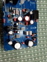
I attached some closer up pics of one board.
Yea, when I was mounting the transistors to the heatsinks I accidentally swapped them and then managed to miss the board position numbers id written on the connectors when assembling... I definitely feel like a huge dummy to say the least.
I'd re-checked component values across the board and couldn't find anything out of place. My thought was perhaps v232 got cooked.
I'll get working on the additional info, I appreciate the help for sure!
I attached some closer up pics of one board.
Attachments
I think we have all made a similar mistake before. Similar to having flipped rail polarities. Expect smoke and fireworks and generally, MOSFETs or BJTs die. Sorry about your amp. Hopefully you can recover and not have any major damage.
I still owe ya a comprehensive list of in circuit measurements, but in the mean time I have removed/tested nearly every diode/bjt/mosfet (using a cheapo DROK tester: seems to work fairly reliably?). Confirming the tester results to their spec sheets at least seems like all of them are fine. I haven't removed v101/v105 yet. I've also re-double checked every resistor as well, I have not checked any capacitor yet. I don't see how this would cause an issue with the rail voltages but I did end up catching that I populated 1500uf rail caps instead of 15000uf for 204/206/224/226.
Hey folks, waking this thread and this project up. The ABBB PCB’s are now on sale - two for the price of one, so 1 pair is $40. Boards are 2mm thick, 2oz copper, ENIG finish. Nicely made and gives you a complete Class A amp solution that includes a state of the art PSU and SSR speaker protect all on one board.
https://xrkaudio.etsy.com/listing/716039535
https://xrkaudio.etsy.com/listing/716039535
- Home
- Group Buys
- The Alpha Big Boy with Buttah (ABBB) 52w Class A Amp GB