Gain is set by resistor R154 and R113 and equal to (18k+680R)/680R=27.5x or 28.8dB.
Great that gain can be configured - is there any rule for adjusting R154 and R113, or can both be changed in any combination to give the desired gain?
Heat gain is too much for me into 4 Ohms, so I'll stick with 8 Ohms.
It is better to keep the feedback R154 constant and adjust R113 (680R) but don't change to too much. Hugh can respond more definitively but I would keep gain in the range 15dB to 35dB.
Just finished assembly of my boards.
Quick question,
There is an extra hole next to the connector to the bjt flying leads. What is this hole for?
A few notes to other builders.
I used the BOM/loading guide that I assembled and uploaded. See the very first post in this thread for a link to the BOM. The only error in that BOM is it is missing a 10k resistor (R227). This is a current dropping resistor for the power supply LED, so hopefully you already have some of those laying around. Nothing special needed.
Huge thanks for the folks that assembled the first BOM's and did the error checking. Parts selection is an unpleasant enterprise and very time consuming. All I did was double check everything, create a map for where everything goes, and replace a few connectors/terminals.
This is not a newbie project, since it does require some skill with a soldering iron.
The board is very well laid out, and there is plenty of room to maneuver on the back side. There are a great deal of large copper pours which can make it difficult to wet the entire pad and not fry the part at the same time. I have a $48.00 Hakko 862 clone whose tips do not make good contact with the heating element, so the tip is slow to respond when a copper pour sucks all the heat out. So some experience is needed with dealing with this sort of thing. Don't be afraid to turn the heat up to 400, just get the tip in and out quickly. With a low watt iron at a lower heat setting, it can take too long to heat the pad, and you end up with fried parts.
The good news is that there are a ton of resistors to practice on, and let you get the feel for how the board solders before you move onto the caps.
The board also de-solders nicely, so if you accidentally put and R where a C goes (don't ask), you don't have to fuss over de-soldering.
I also suggest being really conscience about installing the parts in order of the their height. Some of the parts will be very difficult to place when surrounded by towering caps.
Don't forget a blob of silicone under the bigger caps.
My transformers arrived today 🙂
I'm still on the fence about heatsinks. I have 4 that are rated at 130w, they are the same face dimension as the FD841, but about 2/3 the thickness. Considering how dinky it is, I expect the fan will have to run faster than I want it to. FD841's are expensive, and the little 80mm fans that fit it are expensive if you want quiet ones.
The typical solution to loud computer fans is to use a bigger fan that runs slower. So there is a plethora of 120mm heatsink/fan combos out there that have more heatpipes, more surface area, and lower cost than a used FD841 and a quiet fan.
One thing is clear to me, heatpipes are probably essential. I just wish folks published dissipation ratings for their CPU coolers.
I have a few other things to figure out before I bolt the whole mess to a piece of scrap. I'll report back soonish 🙂
-Josh
Attachments

Nice work, Joshua! No, it’s no beginner’s project due to the size and heat and power.
But it has everything you need integrated into one board that makes it simple.
But it has everything you need integrated into one board that makes it simple.
Conversion
Big apology, I have not been back to this page since I posted the converted pdf. Here is a link with a how-to-convert, quite quick and easy. I just had to search for the tool at the time. Hadn't used it in ages.
Regards, Kevin
How to convert a color PDF to grayscale | Converting PDF
Hi X,Hi Kevin,
Thank you for doing that! Perfectly readable and printable now on B&W laserprinter. In Adobe Acrobat Pro, how do you do the conversion?
Cheers,
X
Big apology, I have not been back to this page since I posted the converted pdf. Here is a link with a how-to-convert, quite quick and easy. I just had to search for the tool at the time. Hadn't used it in ages.
Regards, Kevin
How to convert a color PDF to grayscale | Converting PDF
Last edited:
Cool setup gtose!
X pretty much covered start up, it’s a drama free amp to work with.
The tips I will add are:
-double and triple check you’re flying lead Molex connectors to make sure the wires are oriented correctly.
-Increase R308 from 100K to 150K
- you will have 1v or less adjustability with the trim pots on capMX, adjust for the lowest setting so both positive and negative are equal.
- Working voltage with a 32V transformer is between 37-38vdc.
Happy Building!!
Can I get a clarification on this please.
In particular, what is meant by "lowest setting?"
pots turned in to "lowest setting?"
Voltage rails at "lowest setting?"
voltage drop over the pot at "Lowest setting?"
I'm sure there are other innocent ways to mis-understand this.
Thanks.
-Josh
P.S. Any other set up instructions? I got the message to make sure the leads are both connected and wired properly.
Before installing the output transistors, check to make sure the cap multiplier of the ABBB amp is working properly by adjusting pot to change the output voltage. I think lowest means adjust until the output voltage is the lowest (maximum voltage drop). But adjust them so that they are equal.
Instructions? Naw!!! This is DIY! 🙂
1. Check the PSU section is working properly before installing output MOSFETs. Easy to do by unplugging the Molex quick connectors.
2. Make sure the MOSFETs are not accidentally grounded somehow with continuity meter. Check to make sure you don’t have N and P channels mixed up. Make sure Cap Mx pass transistors are plugged into the board.
3. Connect alligator clips across output source resistor on one of MOSFETs to check for bias current. Current should be about 3A and IIRC, resistors are 0.22ohms? So you should not see too much more tha 0.66V on the DVM when turning on.
4. Wear safety goggles and stand back a good distance while still able to turn on (via a power strip with switch) and able to see DVM.
5. Flip the switch and observe DVM, if it is much more than 0.66V, immediately turn off and investigate. Hopefully no smoke and nothing exploded. The max current should be reached in about 1-2 seconds. If you hear a loud hum sound like the trafo is vibrating turn off immediately before wires glow red hot. A fuse in your mains IEC connector shell should have popped before that happens.
If you have a Variac, it’s easier and less white knuckle. Although these amps are adjustment free - no DC offset or bias current t pots to tweak.
A light bulb tester might work but a 3A Class A load will make the bulb glow for sure. So not useful like for Class AB amps.
Last edited:
Before installing the output transistors, check to make sure the cap multiplier of the ABBB amp is working properly by adjusting pot to change the output voltage. I think lowest means adjust until the output voltage is the lowest (maximum voltage drop). But adjust them so that they are equal.
Hi Joshua43214,
Yes, the above comment is what I meant 😉
Max voltage drop.
Hi folks, I got one of my amps fired up and running, then I let some of the magic smoke out after I moved it. I had let it run for a good 2 minutes or so on my bench to make sure it would not catch fire or otherwise mis-behave, then I moved it to my computer so I could monitor the temps.
Not sure if the PNP grounded against something, or the 10ohm R126 resistor melted. I had to use one from my emergency stash (story not worth telling) - they are 1/2amp rated, but they are also Ebay specials...
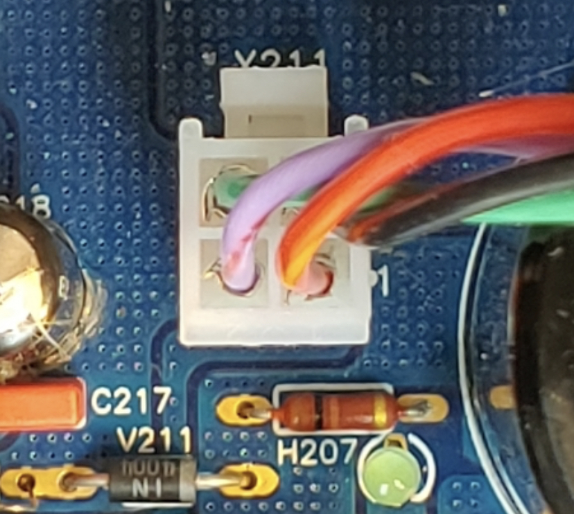
Either way, the PNP lit up, R126 and R214 are smoked, and C218 swelled up.
Before I moved it, I did take a couple of voltage readings.
Voltage drop over R145 (the source resistors) was about 0.6V
Voltage rails measured ~+/-41V
First question:
I'd like to lower the rail voltage to closer to the 38V the amp is supposed to run at. How would I do this?
Second question:
What parts should I expect to replace?
I plan to replace the following:
R126
R214
V211 (diode)
C214
C218
C217
Should I worry about the BJT (V212), or the caps that are on the base side of the BJT (C216, C211)?
Third question:
Is anyone checking temps with an actual sensor rather than a laser device?
Thanks,
-Josh
I know someone here powered up their ABBB with the transistors unplugged and smoked part of their board.
EDIT:
I fixed the resistor ID in parts I intend to replace
Not sure if the PNP grounded against something, or the 10ohm R126 resistor melted. I had to use one from my emergency stash (story not worth telling) - they are 1/2amp rated, but they are also Ebay specials...
Either way, the PNP lit up, R126 and R214 are smoked, and C218 swelled up.
Before I moved it, I did take a couple of voltage readings.
Voltage drop over R145 (the source resistors) was about 0.6V
Voltage rails measured ~+/-41V
First question:
I'd like to lower the rail voltage to closer to the 38V the amp is supposed to run at. How would I do this?
Second question:
What parts should I expect to replace?
I plan to replace the following:
R126
R214
V211 (diode)
C214
C218
C217
Should I worry about the BJT (V212), or the caps that are on the base side of the BJT (C216, C211)?
Third question:
Is anyone checking temps with an actual sensor rather than a laser device?
Thanks,
-Josh
I know someone here powered up their ABBB with the transistors unplugged and smoked part of their board.
EDIT:
I fixed the resistor ID in parts I intend to replace
Last edited:
Hi Josh,
It’s been a while since I have looked at this amp. Can you please markup the schematics with the parts that burned out and indicate the voltages you measured before it blew up.
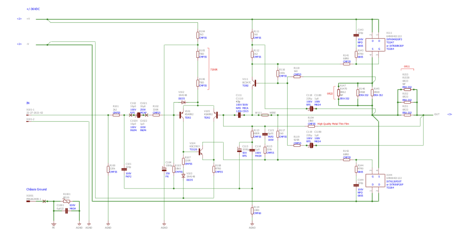
It’s been a while since I have looked at this amp. Can you please markup the schematics with the parts that burned out and indicate the voltages you measured before it blew up.
Hi Josh,
It’s been a while since I have looked at this amp. Can you please markup the schematics with the parts that burned out and indicate the voltages you measured before it blew up.
Hi X, thanks for the quick reply.
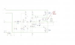
Here you go
I marked an X on the 3 parts that are visibly damaged.
I circled the parts I believe should be replaced for good measure.
Thanks again,
-Josh
Attachments

Hi Josh,
That stinks, no pun intended, that you got the dreaded black smoke.
It looks like there is an issue with the PNP section.
-What transformer are you using?
-Did you triple check that your flying lead connections are correct and that the socket pins are seated in the Molex Minifit connectors.
-Post detailed pictures of your ABBB board and your flying leads/transistors.
Josh,
If you blow up an electro, it's usually overvoltage, or reverse polarity.
Check that the outputs from the bridge is OK, say at 50V at least wrt ground.
Then check that the A1943 pass transistor is not fused, and check base to emitter of the driver under that big transistor is 0.65V running.
Hugh
If you blow up an electro, it's usually overvoltage, or reverse polarity.
Check that the outputs from the bridge is OK, say at 50V at least wrt ground.
Then check that the A1943 pass transistor is not fused, and check base to emitter of the driver under that big transistor is 0.65V running.
Hugh
Josh,
If you blow up an electro, it's usually overvoltage, or reverse polarity.
Check that the outputs from the bridge is OK, say at 50V at least wrt ground.
Then check that the A1943 pass transistor is not fused, and check base to emitter of the driver under that big transistor is 0.65V running.
Hugh
The A1943 is not only fused, it caught on fire 🙂
Keep in mind, the amp ran for a couple minutes just fine before I moved it to my desk so I could monitor the temps.
I am leaning towards the cause of failure being either the transistor shorted to something, or the Ebay Special R126 blew taking the rest with it.
I'll get your voltages once new parts arrive.
@Vunce
I will get some pics together in the morning showing the board and flying leads. I will also upload the charts I used to verify the flying leads are correct. I checked many times, in many ways.
EDIT: I am using an Antek AS-6432 traffo
Thanks again for all your help,
-Josh
Oscillation? If it worked and then blew up, that’s sort of the signature. When you moved it, how is the setup different at the desk? Is this mounted in a chassis or heatsink? The big BJT needs to be on a heatsink.
Also, make sure the series pass transistor (2SA1943) is electrically isolated from the heatsink.
Hi all, sorry for the delay. Work has kept me busy this week.
I ordered replacements for what I knew was blown, and what was available for the rest.
To address a few comments/questions first:
The BJT was isolated from the heat sink, and the whole mess is screwed to some MDF.
Reverse polarity is unlikely since it ran for a couple minutes. Either the Chinese 10 ohm resistor I put in the board blew, or I left something on the desk that shorted the BLT legs.
I checked, rechecked, then checked and rechecked again. It was a couple of weeks between making the connectors and powering it up, and I checked and rechecked again at that time. I checked alot 🙂
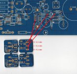
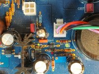
Attached is a pic of board. I drew lines connecting the BJT legs to the pads on the board where I measured. All resistances where under .4 ohm before it blew, and are all under .4 ohm after parts replacement.
Attached is a pic of the amp before replacing the parts. I put a red dot next to the Chinese resistor (10ohm) that blew. I put a yellow dot next to the 68ohm Vishay resistor that also appeared blown.
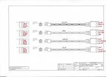
Attached is a pic of the connector diagram showing the wires, and a pic of the wires themselves.
The parts I replaced are:
R126 10ohm resistor
R214 68ohm resistor
V211 diode
C214 ceramic cap (SMD)
C217 flim cap
C218 electrolyte cap (it was blown)
Mouser was out of the board mounted transistor.
Any suggestions before I put power to it?
I feel pretty confident things should go fine if I leave the power MOSFETs disconnected, and use a light bulb in series with the power chord.
As always, I really appreciate you folks taking the time to help.
Thanks,
-Josh
I ordered replacements for what I knew was blown, and what was available for the rest.
To address a few comments/questions first:
The BJT was isolated from the heat sink, and the whole mess is screwed to some MDF.
Reverse polarity is unlikely since it ran for a couple minutes. Either the Chinese 10 ohm resistor I put in the board blew, or I left something on the desk that shorted the BLT legs.
I checked, rechecked, then checked and rechecked again. It was a couple of weeks between making the connectors and powering it up, and I checked and rechecked again at that time. I checked alot 🙂
Attached is a pic of board. I drew lines connecting the BJT legs to the pads on the board where I measured. All resistances where under .4 ohm before it blew, and are all under .4 ohm after parts replacement.
Attached is a pic of the amp before replacing the parts. I put a red dot next to the Chinese resistor (10ohm) that blew. I put a yellow dot next to the 68ohm Vishay resistor that also appeared blown.
Attached is a pic of the connector diagram showing the wires, and a pic of the wires themselves.
The parts I replaced are:
R126 10ohm resistor
R214 68ohm resistor
V211 diode
C214 ceramic cap (SMD)
C217 flim cap
C218 electrolyte cap (it was blown)
Mouser was out of the board mounted transistor.
Any suggestions before I put power to it?
I feel pretty confident things should go fine if I leave the power MOSFETs disconnected, and use a light bulb in series with the power chord.
As always, I really appreciate you folks taking the time to help.
Thanks,
-Josh
Attachments

Hi Josh,
The resistors you show as burning out fail when the connection between the PCB and cap Mx BJT goes open circuit. The fact that it was working at one point shows that it was correctly built. The only thing I can see is that in moving it, one of your connections was loose or became loose, and on power up - all the Class A current (3A of it) passes through the little resistors because of lack of path to pass through the BJT collector/emitter path.
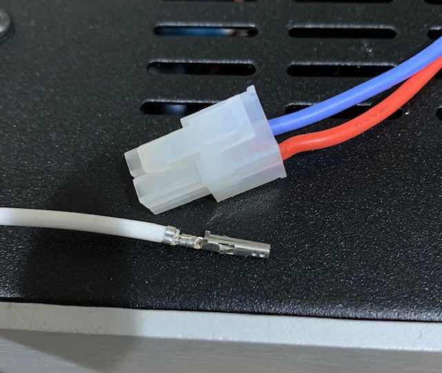
Please check your Molex Minifit connectors. Did you crimp the wires properly with a real crimp tool or maybe improvised with needle nose pliers?
Your photo closeup shows pins that don’t look properly crimped. I see wings of the connector that are not tightly crimped around the wire. It should look tight and cylindrical. You may need to invest in a set of crimper pliers.
A good crimp connector looks like this:
Here is tool I use -Iwiss brand. Many people like the “Engineer” brand.
The SLB (Smooth Like Butter) Active Rect/CRC/Cap Mx Class A Power Supply GB
Thanks,
X
The resistors you show as burning out fail when the connection between the PCB and cap Mx BJT goes open circuit. The fact that it was working at one point shows that it was correctly built. The only thing I can see is that in moving it, one of your connections was loose or became loose, and on power up - all the Class A current (3A of it) passes through the little resistors because of lack of path to pass through the BJT collector/emitter path.
Please check your Molex Minifit connectors. Did you crimp the wires properly with a real crimp tool or maybe improvised with needle nose pliers?
Your photo closeup shows pins that don’t look properly crimped. I see wings of the connector that are not tightly crimped around the wire. It should look tight and cylindrical. You may need to invest in a set of crimper pliers.
A good crimp connector looks like this:
Here is tool I use -Iwiss brand. Many people like the “Engineer” brand.
The SLB (Smooth Like Butter) Active Rect/CRC/Cap Mx Class A Power Supply GB
Thanks,
X
Attachments

Last edited:
- Home
- Group Buys
- The Alpha Big Boy with Buttah (ABBB) 52w Class A Amp GB