Hi Jaytor,
I missed the part of your question regarding the chassis. My answer was purely from the transformer aspect.
Your chassis probably can’t handle the power dissipated by these MOSFETs.
Your transformer will make about 35v no load. It will sag about 4v under Class A load. Then another 3v drop across the cap Mx.
So that’s 28.3v x 3A is 84w per mosfet or 170w per channel. You need a huge heatsink like 5U x 400mm maybe that isn’t enough.
CPU coolers and fan is the way to go.
Thanks for the clarification. Oh well...I really want to stick with passive cooling, so I'll have to keep looking for something that will work, at least for this build. What I'd love to find is a push-pull amp that I can bias to run 15-20W class A but with enough voltage swing to run to 40W or so in A/B. Also hoping to find something that will be a step up from my Parasound JC5 when driving efficient speakers.
Try the Alpha Nirvana. It makes about 90w dissipation per channel and is 40w into 8ohms with the same trafo. It’s more efficient and pure Class A. It might be what you are looking for. It will require the SLBthat you already ordered. It is a superb sounding amp.
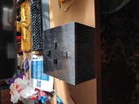
For anyone looking for a cost effective and compact low cost chassis for an ABBB build, here are some ideas using an ITX computer chassis from ThermalTake.
Alpha Nirvana 39w 8ohm Class A Amp
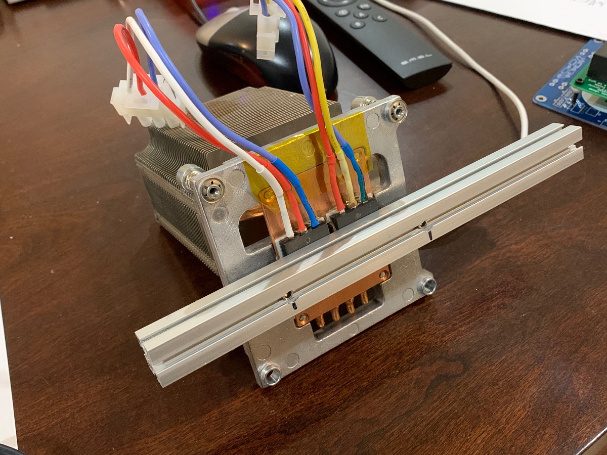
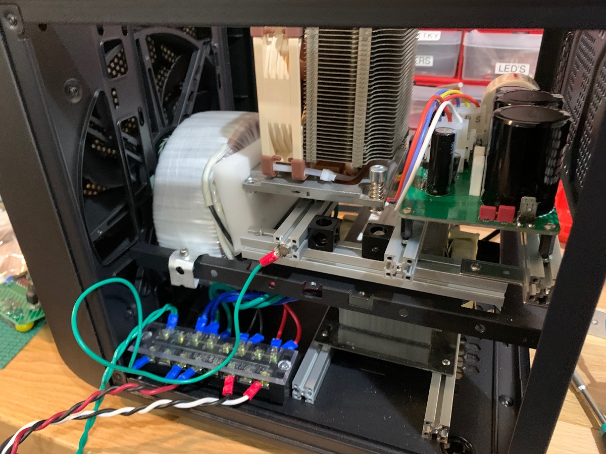
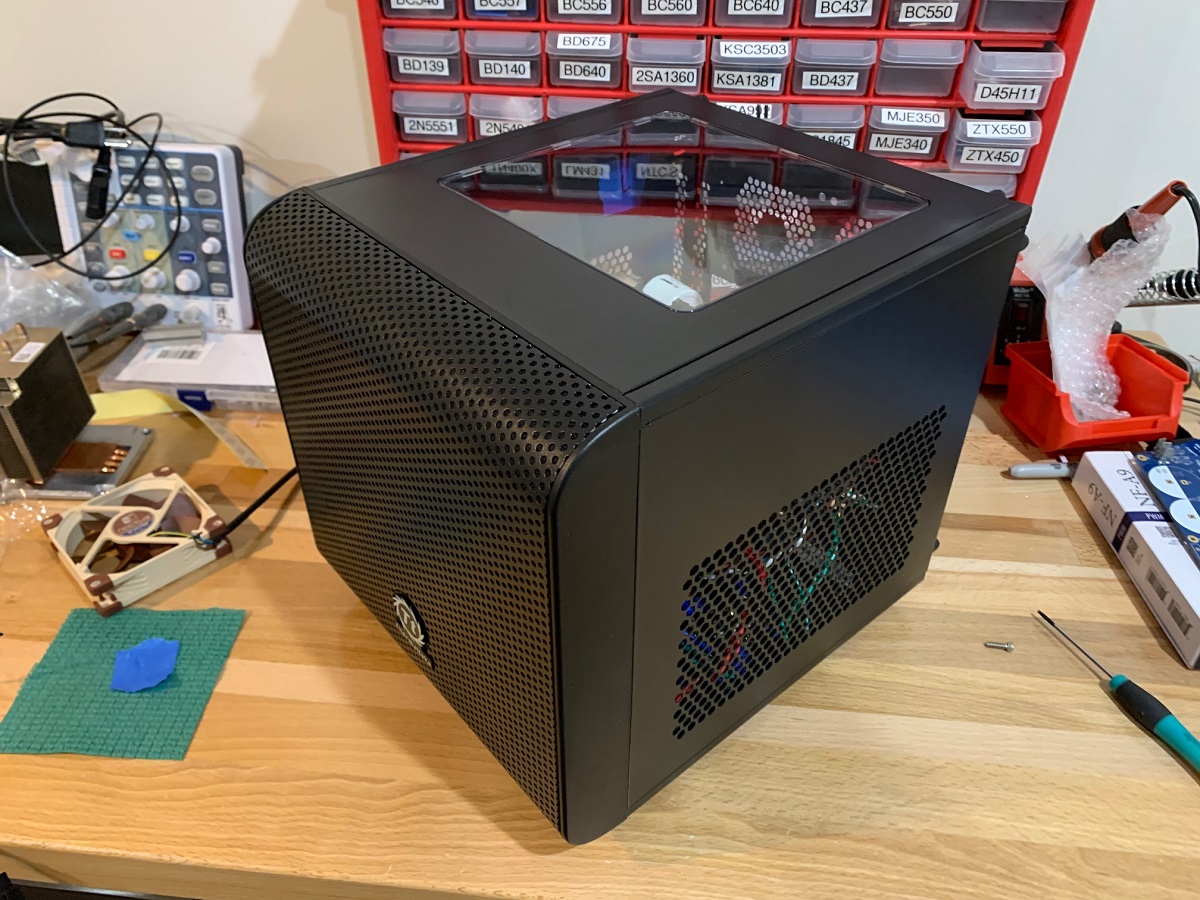
I used MakerBeam XL extrusions to form the framework to hold all of the internal bits and pieces in a nice rigid frame that required minimal cutting/machine work.
Alpha Nirvana 39w 8ohm Class A Amp
I used MakerBeam XL extrusions to form the framework to hold all of the internal bits and pieces in a nice rigid frame that required minimal cutting/machine work.
Very cool X, compact, smart, and high tech!
With these cases it is possible one can be mistaken as a computer nerd instead of crazy audio guy! 😉
With these cases it is possible one can be mistaken as a computer nerd instead of crazy audio guy! 😉
Hi X,
My apologies, I asked in a previous post if it is possible to use a total of four power FETs instead of two to spread the heat load? (please note I am not an electronics expert.) I'm have a BJT based (MJ802) 25W Class-A amp and 4 devices are used to spread the heat load, to keep all the devices within a "comfortable" operating area. I do understand that the power FETs can take a lot of punch, but if I wanted to, would it be possible to add adiditional power FETs?
Regards,
Kevin
Hi Kevin,
This amp has a 3A bias current x +/-36v rails. At 4 MOSFETs that’s about 54w dissipation each. If you use IXYS high power ones that can work but your heatsink will be huge. About 8U x 300mm deep or equivalent. Maybe 5U x 400mm can work.
All those heavy aluminum fins cost a lot of money. But if you have it already, then, yes it can work. You will need to match the MOSFETs.
Note that adding MOSFETs increases capacitance of gate and the drive circuit would have to be reconfigured. I will let Hugh give the final recommendation. Also I think you are saying 4 MOSFETs total not 4 per rail for 8. That would be way too many, and going back to old way of doing things. Keeping one pair of MOSFETs gives cleaner and more articulate sound.
Last edited:
Questions? Ask and learn.
Hi X,
No I actually did mean a total of 8 (4 per channel) so that the current per device (and thus heat) could be lower per device - 1.5A quiscent current and not 3A. However I do understand your explanation re the gate capacitance and having to reconfigure the circuit accordingly. As I said I am very much a newbie, and can follow BJT circuits better than FETs. But I am slowly starting to catch on. Excuse my ignorance, but I firmly believe in asking if I don't understand, and in that way learn. I'm getting there slowly.
I only started seriously following electronics when I joined in 2008, but that was interrupted by a big down turn in my life 'tween 2011 - 2015. I have a lot of catch up to do. I never studied electronics in any way whatsoever (qualified civils tecnician, 3 years timber research and then IT - PCs and now networking and cabling specialist.) Have NEETS, and very slowly working through it.
Many thanks, Kevin
Last edited:
If you are looking for a set of ABBB pcbs, please check the Swap Meet forum under thread Class A pcb's. Good prices. X gave me permission to post here.
Regards
Regards
I cannot remember if I ever posted the PDF files for the schematics for the production version yet. Sorry if you had a hard time finding them. DrPro was telling me he had a hard time reading the current ones. Also included are teh stuffing diagrams and the BOM in Excel format (zip file). I will link this post in post #1.
I find that printing the schematics from the Adobe Acrobat PDF viewer program with 600dpi and print grayscale works best for b&w powder toner laser printers.
Let me know if you need anything else. I may ask JPS64 to generate some all "black only" pdf schematics for us old timers who like to use b&w laser printers.
Thanks,
X
Attachments
Last edited:
Hi Kevin,
Thank you for doing that! Perfectly readable and printable now on B&W laserprinter. In Adobe Acrobat Pro, how do you do the conversion?
Cheers,
X
Thank you for doing that! Perfectly readable and printable now on B&W laserprinter. In Adobe Acrobat Pro, how do you do the conversion?
Cheers,
X
Anybody in need of a pair of ABBB boards ($30USD + shipping) or BB boards ($20USD + shipping). PM me if interested.
Keep safe and well,
MM
Keep safe and well,
MM
Passive cooling
I really want to stick with passive cooling also. I have a heatsink with dimension 21,5 x 20 x 11,5cm and weight 6,3 kgr. For each channel. Is it possible ?
I really want to stick with passive cooling also. I have a heatsink with dimension 21,5 x 20 x 11,5cm and weight 6,3 kgr. For each channel. Is it possible ?
36v x 3A= 108w (X2) = 216w per channel.
Unfortunately, I do not think your heatsinking is adequate. CPU coolers/silent fans are really the ideal for this amplifier.
Unfortunately, I do not think your heatsinking is adequate. CPU coolers/silent fans are really the ideal for this amplifier.
X,
are you have the same opinion?
Mayby the heatsink is suitable for Alpha Nirvana?
Or with a fan added?
Thank you in advance
are you have the same opinion?
Mayby the heatsink is suitable for Alpha Nirvana?
Or with a fan added?
Thank you in advance
Add a fan and you’ll be fine. Those fins are very narrowly spaced and probably designed for fan and not natural convention anyway. A 200mm Noctua would be perfect size.
This is a great project...
What is the gain?
Is it capable of 4 ohm speakers (how many watts into 4 ohms?)
What are ixys mosfet's?
Gavin
What is the gain?
Is it capable of 4 ohm speakers (how many watts into 4 ohms?)
What are ixys mosfet's?
Gavin
Gain is set by resistor R154 and R113 and equal to (18k+680R)/680R=27.5x or 28.8dB.
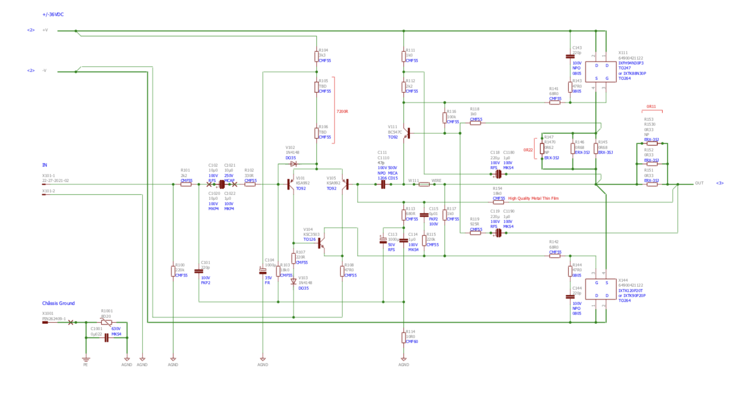
To get 4ohms is possible and discussed in the other Alpha 20 amp thread. Rail voltage would need to be reduced and bias current would have to be increased. The maximum thermal dissipation will be about 160w per MOSFET assuming you are using 1 CPU cooler per MOSFET. The IXYS are large power MOSFETs spec’d for this amp. They can handle up to 600w dissipation but CPU coolers typically rated 150w. Some people have used water cooling setups and I think with that, even 37v at 5A is not a problem or 185w per MOSFET.
For 8ohm bias current is 3A and rail voltage is 37v per side. If we go to 5A bias and set rail voltage at 30v that would be 150w per MOSFET or 300w per channel. It will take some resistors to be changed for setpoints but doable.
Last edited:
- Home
- Group Buys
- The Alpha Big Boy with Buttah (ABBB) 52w Class A Amp GB