Nigel - can we tweak the gain of the power amp without changing the sound signature away from the 'Naim' ? Reducing the sensitivity makes sense with a pre-amp with some gain. Increasing sensitivity removes all need for gain in the pre-amp but reduces the feedback factor in the power amp and increases distortion which may not be desirable. It may in fact be a more interesting idea to reduce the amplifier sensitivity and get a bit more distortion reduction from the negative feedback.
I think we can and be even more in the spirit of JV. As we have Cdom killing the loop gain we can have a higher amplifier gain with more or less identical HF distortortion if we relax Cdom a bit. It's a very valid upgrade that should have no " real " downside. DC offset might hit 4 mV and hiss go from at a guess - 106 dB to - 100 dB. If you soldered another 1K to the feedback lower arm and an extra feedback cap you would quickly know. I suspect Cdom would be 27 pf. I would base this design on the buffer and a CD player as my starting point. From what I have read NAP 140 distortion is very low below 7 kHz. The distortion rises at 7 kHz due to Cdom mostly and not the simple amplifier set gain.
The easiest way to decrease PSU output impedance by a factor of 100X, is to increase the open loop gain of its error amplifier by a factor of 100X, since
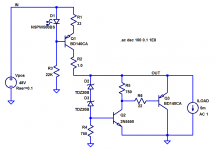
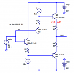
In the circuit of post #134 image_1, that would mean replacing R16 by a current source, and also replacing Q7 by a Darlington or a CFP/Sziklai (drastically reducing its loading upon the collector of Q6).
- Zout_closedloop = Zout_openloop / (1 + openloopgain)
In the circuit of post #134 image_1, that would mean replacing R16 by a current source, and also replacing Q7 by a Darlington or a CFP/Sziklai (drastically reducing its loading upon the collector of Q6).
Last edited:
Member
Joined 2009
Paid Member
In the circuit of post #134 image_1, that would mean replacing R16 by a current source.
This was my thought too, but then I wondered if this is feasible ? - there's very little voltage headroom here, R16 drops only 650mV since it sits between base-emitter of the shunt transistor. This is why I simulated an extra gain stage, another BJT cascaded to the design I posted. It increases the OLG as you say, by around 20dB if I remember. I can't post any attachments from my simulation right now as I'm not at my usual computer.

Member
Joined 2009
Paid Member
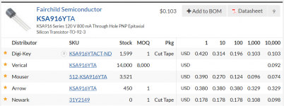
that's a nice low Vce(sat) - I'll try a simulation on this one, looks promising indeed. I may opt for an SMD transistor, I'll check the Digikey catalogue for options.
Edit: e.g. BSS63LT1G from On-Semi
https://www.digikey.ca/product-detail/en/on-semiconductor/BSS63LT1G/BSS63LT1GOSCT-ND/2120567
Edit: e.g. BSS63LT1G from On-Semi
https://www.digikey.ca/product-detail/en/on-semiconductor/BSS63LT1G/BSS63LT1GOSCT-ND/2120567
Last edited:
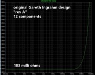
The positive half of Gareth Ingram's dual regulator in post #134, uses 12 components. Its output impedance at low and medium frequencies is 183 milli ohms. See "rev A" below.
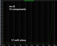
If we make a slight alteration to the design, following one of the suggestions in post #162, the component count rises to 13 parts, while output impedance is cut by a factor of eleven, to 17 milli ohms. See "rev B" below.
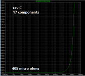
If we make a second alteration, following the other suggestion in #162, component count zooms up to 17 parts, and output impedance falls another factor of 40X, to 0.405 milli ohms. See "rev C" below.
Regrettably, these alterations do include "original research" as Wikipedia puts it; they are not pure copies of a published, working, known good design from a celebrated Name Designer. So they may not align with the philosophical goals of this project 🙁 However the simulated performances are quite pleasant.
_
If we make a slight alteration to the design, following one of the suggestions in post #162, the component count rises to 13 parts, while output impedance is cut by a factor of eleven, to 17 milli ohms. See "rev B" below.
If we make a second alteration, following the other suggestion in #162, component count zooms up to 17 parts, and output impedance falls another factor of 40X, to 0.405 milli ohms. See "rev C" below.
Regrettably, these alterations do include "original research" as Wikipedia puts it; they are not pure copies of a published, working, known good design from a celebrated Name Designer. So they may not align with the philosophical goals of this project 🙁 However the simulated performances are quite pleasant.
_
Attachments

Last edited:
Member
Joined 2009
Paid Member
The project goals didn't exclude some engineering improvements 😀
I think it's worth looking at the stability of the regulator, it's a high gain feedback loop and there will be capacitance and who knows what else on the rails.
I think it's worth looking at the stability of the regulator, it's a high gain feedback loop and there will be capacitance and who knows what else on the rails.
My little preamp instrumentation power supply uses a single low cost opamp
and gives quite pleasant Line Rejection (a/k/a PSRR) across the spectrum from DC to supersonic. But some people refuse to even think about using opamps.
And what is the Zout of this one?
https://www.youtube.com/watch?v=AluHfglOxyIAny thoughts on the use of a single ended discrete single FET output for a headphone amp
I have seen it with LM317 CCS. My two BC337's works well, one as a CCS ( sink ). I don't think people realised the 337's were in place to improve a general purpose op amp by taking the workload off of the op amp. The bonus was driving headphones if required.
I was thinking. Diamond buffer with high voltage ( +/- 30 ) voltage amp and CCS. It could rival many op amps. We should be thinking of a very high input impedance into the buffer so who knows how good it could be. PDF gives some idea.
http://www.ti.com/lit/an/snoa725a/snoa725a.pdf
I was thinking. Diamond buffer with high voltage ( +/- 30 ) voltage amp and CCS. It could rival many op amps. We should be thinking of a very high input impedance into the buffer so who knows how good it could be. PDF gives some idea.
http://www.ti.com/lit/an/snoa725a/snoa725a.pdf
Member
Joined 2009
Paid Member
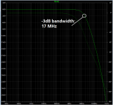
One of the worries with the Diamond Buffer is the bandwidth is so large that I feel inclined to hobble it somewhere just to remove the risk of something untoward.
Brian - what the heck is a sumo wrestler dancing got to do with single ended FETs !!?
Brian - what the heck is a sumo wrestler dancing got to do with single ended FETs !!?
As said before and RC filter at the output would serve well. I think I will build the L0002 as they were so kind as to tell me how.
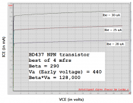
Implement the diamond using the complementary pair BD437/BD438 . Automatic, guaranteed bandwidth limiting via device selection.
BTW the NPN device has one of the highest Bob Cordell transistor figure of merit numbers (FOM = EarlyVoltage * Beta) that I've ever measured.
_
BTW the NPN device has one of the highest Bob Cordell transistor figure of merit numbers (FOM = EarlyVoltage * Beta) that I've ever measured.
_
Attachments
Member
Joined 2009
Paid Member
good find, I've never used these devices but they're readily available from Digikey for a buck.
Member
Joined 2009
Paid Member
I'm realizing that we are spoiled for choice. The solutions available to us are really very good, whether an op-amp or a discrete diamond buffer or other ideas (except not dancing sumo), we have the means to create a simple, affordable solution with amazing performance. It almost seems a shame to have to choose.
You still need to find a good gain stage design. I think you need some gain in the signal path for versatility, like up to 10x. Once you have some gain you can tack on a buffer to drive headphones.
I favour a discrete gain stage. I'll see what I can find; something simple like the NAC and maybe we can throw a JFET in the input cause they're sexy. Well, John Curl thinks so. Some claim high-end mfrs use JFETs because they are cheap. They do have the advantage of high input Z but they have feeble transconductance which needs to be taken into account.
All fun.
PS: I thought that Sumo video summed up mosfet followers quite well. 😀
- Status
- Not open for further replies.
- Home
- Source & Line
- Analog Line Level
- TGMC - a modular control pre-amplifier