Member
Joined 2009
Paid Member
PSRR and regulators
PSRR
Let’s think about this topic a bit because I think it’s central to the performance of this preamp.
The first thing to get out of the way is the upstream crap from the power supply which is needed to give this project a solid foundation. There’s an upstream regulator, a voltage regulator based on the venerable LM317/337. This is a classic topology and the i.c. incorporates a proven but dated op-amp. The output will be a steady +/-36V and will be free of power supply ripple but it's not of the lowest noise type and we don’t want any signal currents getting near it.
The circuit boards will have their own shunt regulator. This provides a return path for any signal currents on the power supply rails from the active circuits and isolates them from the upstream regulator and from the ‘other’ channel.
Unless each circuit (phono, gain, buffer) have their own shunt regulator there can be interaction between these circuits via the power supply rails. Designing the shunt regulator with very low output impedance across a wide frequency range should deal with this. The only concern I have about that is such low rail impedance implies a high feedback factor shunt regulator, which is subject to the same challenges in terms of stability, ringing and other consequences as any high feedback amplifier.
The buffer circuits have a naturally high PSRR. The phono amp does not. The phono amp is an interesting topology. The input stage/error amplifier for feedback loop is a Rush Cascode who’s output feeds an emitter coupled amplifier with the output loaded on a CCS. This arrangement has poor PSRR. There will be signal current flow through the power rails. So any crap on the power rails generated by other circuits sharing these rails could be audible. The signal currents from the output buffer will also flow through the external load, whatever that might be.
An option for the phono amp circuit that I mentioned a few posts back is to add capacitance multipliers to the power rails but because the return path for signals from the phono through the power rails these capacitance multipliers might be ‘audible’. Nelson Pass found the ‘cure’ for power amps was lots of passive capacitance on the rails after the multiplier. As the phono amp already uses a big electrolytic cap in the signal path (feedback shunt) there’s little justification to be getting fussy about using a big electrolytic on the power rails. However, another option is to provide a separate, dedicated shunt regulator for just the phono amplifier. This maybe the ‘royal’ option but perhaps I’m getting off track here into the extreme ?
Last edited:
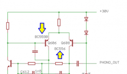
One reason why the circuit in #190 has bad PSRR, is because Q6 and Q7 are design errors. Someone has built a current source which drives an infinite impedance load (!). This guarantees it will pull its collector node all the way up to Vcesat, changing it from a current source into a low impedance path to the noisy input.In LTSpice this phono section has atrocious PSRR,
...
You'll get much better performance if you just use two resistors and two capacitors to f-f-f-filter the MOSFET gate node. Protip: make the first capacitor an RF "feedthrough" capacitor (which is a three terminal device) for best real world performance with nonideal components (unlike SPICE ideal components).
I'm partial to these feedthrough capacitors, but there are many possible choices.
Last edited:
Member
Joined 2009
Paid Member
Interesting little devil that is. I usually buy from Digikey but they also carry these things. However, all their parts based on C0G technology are low voltage. I suspect the higher voltage parts are undesirable for the audio-path as they'll be the non-C0G types. But they could be handy for removing crap after the upstream regulator, between the upstream and downstream.
Last edited:
Some people don't consider the gate node of a MOSFET capacitance multiplier, to be in "the audio-path".
Some people even go so far as to connect (gasp!) electrolytic capacitors to this node.
Nevertheless there is good news for those who insist upon using only film capacitors in their MOSFET capacitance multipliers: you can synthesize the benefits of a feedthru capacitor by implementing its function with discrete parts, none of which are electrolytic or ceramic capacitors. Thanks to the high impedance of the gate node, you don't even need enormous bulky components.
Member
Joined 2009
Paid Member
we can only show them the way and hope for the best 😛Some people even go so far as
(it's called a multiplier because it multiplies whatever is at the gate! be they daemons or not...)
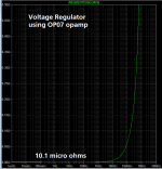
My little preamp instrumentation power supply uses a single low cost opamp and gives quite pleasant Line Rejection (a/k/a PSRR) across the spectrum from DC to supersonic. But some people refuse to even think about using opamps.
And what is the Zout of this one?
10.1 micro ohms. It starts to roll off sooner than you might wish, thanks to the anemic bandwidth of the OP07. But its gain! Wow! Zout falls as gain rises and OP07's gain is ~ 114 dB. There are other "precision opamps" with even higher gain but none are as inexpensive as the OP07.
_
Attachments
The only problem I see with this is Naim only had RC filters after the LM317. Whilst these fashionable circuits have something of a space mission about them I have real doubts they will sound better compared with getting the decoupling right.
I borrowed a top grade oscilloscope once that could do UHF TV frequencies. Inside a CD player the power lines were very dirty right up to the chips. Across the chips decoupling caps it became almost quiet. Sorry guys it is that simple. There are problems doing these measurement. I took enough to feel at least 20% were showing real things. Without exception the decoupling was the big deal. I would recomend a ground plan if wanting to use these advanced regulators. I always thought ground planes the poor relation compared with star grounding. In my work some projects would have been impossible without them. However even they can be trouble.
How about an ampliferd zener followed by a LM317/337. A small RC filter after the zener to aid stability into the bargain. I never have used that idea, wish I had.
Yes.The only problem I see with this is Naim only had RC filters after the LM317. Whilst these fashionable circuits have something of a space mission about them I have real doubts they will sound better compared with getting the decoupling right.
Good quality capacitors are expensive and bulky. It suits some manufacturers to use complicated, active circuits to avoid them and save pcb space. Look inside a mobile phone then look inside an Audio Research preamp.
Aside: why can't a company like Apple with its billions in the bank afford to hire someone talented to make their iPhone audio sound better than a teflon frying pan containing ball bearings?😡
Last edited:
10.1 micro ohms. It starts to roll off sooner than you might wish, thanks to the anemic bandwidth of the OP07. But its gain! Wow! Zout falls as gain rises and OP07's gain is ~ 114 dB. There are other "precision opamps" with even higher gain but none are as inexpensive as the OP07.
_
I dont have the need to design power supply so i dont know yet the secret of a good sounding power supply. It seems that there is a critical variable other than line regulation, noise and impedance.
If opamp based supply is not good enough by itself, but it will sound acceptable when in front of it there is LM317, what do you think is going on? LM317 doesnt ruin the sound even if the noise is quite high. Adding further regulation to reduce noise doesnt hurt even if impedance a bit compromised. So what is going on with LM317, especially, probably, at its input?
Another aside: the latest pre from Mark Levinson; food for thought.
Mark Levinson No.526 preamplifier | Stereophile.com
Mark Levinson No.526 preamplifier | Stereophile.com
Tinker. Experiment. Try things. See whether X is better than Y, evaluated however you think best. The listening-to-power-supplies experiment detailed in Linear Audio, for example, connected a large number of different voltage regulator PC boards, to one single piece of audio equipment, and recorded listener's subjective assessments of enjoyment and audio quality. But maybe that one single piece of audio equipment they chose, is unrepresentative of the audio gear that YOU prefer. Tubes vs discrete transistors vs ICs; they only listened to one of the three. High feedback vs low feedback vs no feedback at all; it was only one of the three. Point-to-point wiring vs single sided PCB vs double sided PCB vs dead bug over ground plane; it was only one of the four. Steel cabinet vs. aluminum cabinet vs. nonmetallic (perspex / plexiglass / wood) cabinet; it was only one of the three.
There are many many opportunities to declare that what YOU like is not well represented in someone else's tests. Therefore: do the testing yourself!
There are many many opportunities to declare that what YOU like is not well represented in someone else's tests. Therefore: do the testing yourself!
Wow, count the number of electrolytic capacitors on that Levinson board! Their designers seem not to be afraid of electrolytics at all.
I suppose that they were forced to use a thru-hole mounted connector (at center) to the daughterboard, for high reliability and mechanical strength when the connector is plugged and unplugged. Having thus decided the board would include both SMD and thru-hole, they appear to have used very high value electrolytic capacitors, so high that SMD electrolytics in those values are not available, and that's why there are bunches and bunches of thru-hole radial electrolytics, all over everywhere.
There also appear to be four pairs of TO-126 thru-hole mounted transistors, without heatsinks. Why they didn't use D-Pak instead, is a bit of a mystery, since D-Pak is generally more widely available and cheaper too.
_
Attachments
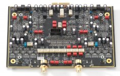
It is fascinating to see what they've used; I imagine cost is not an object. Lots of ICs too. I reckon the line of ICs near the centre are part of the R2R volume control. Lots of relays. I think the main connector is at the far side and is part of the pcb. That middle connector could be anything...often front panel connections.
Read the text of the article too; this picture shows a phono board and it has a daughterboard. That's why there are four silver colored hexagonal standoffs arranged in a rectangle: the daughterboard plugs into the black central connector, and the corners of the daughterboard are bolted to the standoffs.
The relays at front select cartridge loading resistance and capacitance; the relays at rear select gain (for moving coil vs moving magnet).
Since they brag and brag and brag about dual mono mirror image layout, it's unusual to see a single orange component at center top near the edge connector. What would they only want a single copy of?
Member
Joined 2009
Paid Member
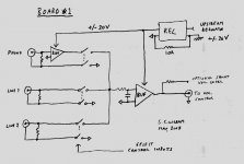
Board1#1
wow, they got a lotta stuff on that board. It would take me more than a little effort to duplicate that and the chances of getting it right first time around are nil. I take my hat off to these guys. JC's Blowtorch pre-amp has <1/10th of the number of parts and probably sounds at least as good though. There's things to learn here but I'm not sure what they all are - do you think relay switching for the cartridge loading is sonically better than a DIP switch (which I've proposed) ?
I'm starting to feel the law of diminishing returns apply to my own project. I don't want to unnecessarily Rush it (play on words there!) but I figure I'd better start on a layout for Board#1. I've decided to forego including an output buffer on this board as space is already tight. So this first board will be the input board, with RIAA and a single buffer that sits in the signal chain just before the off-board volume control.
I need other sets of eyes on this first board or we'll be wasting time fixing it rather than moving on to fun stuff for board-2.
Attached is the Eagle (layout software) schematic entry layer. It looks a bit disjointed so I'll upload a joined-up block sketch of it.
Attachments

Last edited:
Member
Joined 2009
Paid Member
This portion surprises me:
_
these parts choices haven't been reviewed, for the phono they are a direct take-off from the original NAD circuit (attached). I'm not sure why the designer specified these choices. This emitter coupled amplifier is NOT an LTP by the way so matching is not relevant.
my guess:
The BC559 was chosen for it's low noise, at least the datasheet says low noise. The BC556 was chosen for having a higher Vce(max) and is matched to it's complement, the BC546 below it on the schematic as these two devices are paired as a complementary output stage.
Attachments
Last edited:
Another aside:
6moons industry features: RoadTour Nagra
One of the most impressive audio company quarters of one of the most impressive audio companies of all times. And many pictures of their production floor, units, boards... Love the mechanical design... IMO, genius mechanical engineering team.
Different design approach from that of Harman.
Member
Joined 2009
Paid Member
You gotta love their design aesthetic, I mean I've never owned a reel-to-reel but these guys make me want one. If you follow that link, look carefully at the photo of their new amp, in the lab - the design engineer over at the other bench keeps a nice bottle of red wine on the floor. Now that has to be the kind of environment that encourages down-time to reflect on design choices 🙂
I've attached a sketch of the overall scheme for Board#1, including the grounding.
Attachments
This portion surprises me:
_
One would have to look at what is going on there in the simulation. The floating LTP emitters stage?
Last edited:
- Status
- Not open for further replies.
- Home
- Source & Line
- Analog Line Level
- TGMC - a modular control pre-amplifier