Member
Joined 2009
Paid Member
R14=33
R16=750
R19=1K5
You and Gareth sure are miserly with bias current.
I think the final build used some different values, mostly because the LEDs had different voltage drops than those used in the Spice model. The shunt current only needs to be sufficient to cover the current variations in the downstream circuit. More current means higher gm from the shunt transistors and less current variation as a % of total current - both lead to better performance. But higher current means more heat and my first build had inadequate heatsinks - I was uncomfortable with the temperature of the little pcb mounted heatsinks and dialled back the current to as little as I could get away with. Miserly is correct ! For this project, we're gonna bolt these devices to the chassis which provides a considerable improvement in thermal dissipation and that will allow more current.
My little preamp instrumentation power supply uses a single low cost opamp

and gives quite pleasant Line Rejection (a/k/a PSRR) across the spectrum from DC to supersonic. But some people refuse to even think about using opamps.
_
The world would be a different place without the skills of IC designers.
Member
Joined 2009
Paid Member
My little preamp instrumentation power supply uses a single low cost opamp and gives quite pleasant Line Rejection (a/k/a PSRR) across the spectrum from DC to supersonic. But some people refuse to even think about using opamps.
Indeed - there are some amazing op-amps we can use here. I've not worked with fast op-amps before and it's quite an interesting topic. I'm sure if I don't use op-amps on Board-1 there'll be a compelling reason for use on Board-2, in fact I can feel it my bones!
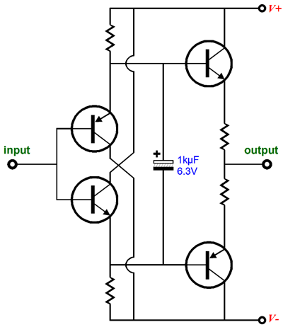
I have looked at a couple of discrete buffer options, just for fun whilst the decision process is still ongoing. I set up an LTspice simulation to get a feel for three options, a) the NAIM 324 board, a single ended CFP loaded on a CCS - this didn't produce the lowest distortion but I expect it could be modified for better results, b) a simple Diamond Buffer with bootstrapped current source - this was lower in distortion, nothing to complain about, c) a more complex Diamond Buffer with bootstrapped power supply ('dadod' used this in his GainWire, 'PigletsDad' has used it - found it originally in an old EW article) - this produces significantly lower distortion.
This bootstrapped-supply DB looks on paper (Spice) to be astonishing. I've posted the schematic below along with my Spice file. I believe Damir's GainWire amp has been built by others and found to be excellent. In which case, it's not a high risk, what's not to like ?
Attachments
Last edited:
Member
Joined 2009
Paid Member
Some further information here (seems Elvee was quite active with this idea too):
http://www.diyaudio.com/forums/solid-state/235500-simple-line-buffer.html
and here (see post #248 for schematic that I showed a clip from):
http://www.diyaudio.com/forums/solid-state/235695-no-nfb-line-amp-gainwire-mk2.html
http://www.diyaudio.com/forums/solid-state/235500-simple-line-buffer.html
and here (see post #248 for schematic that I showed a clip from):
http://www.diyaudio.com/forums/solid-state/235695-no-nfb-line-amp-gainwire-mk2.html
Last edited:
Some further information here (seems Elvee was quite active with this idea too):
http://www.diyaudio.com/forums/solid-state/235500-simple-line-buffer.html
and here (see post #248 for schematic that I showed a clip from):
http://www.diyaudio.com/forums/solid-state/235695-no-nfb-line-amp-gainwire-mk2.html
2N5401 and 2N5551 have high VAF - have you tried these in the Elvee Crazy Diamond Buffer. I suggest using the Cordell models for this purpose.
My thinking is with high VAF any differences in high frequency behaviour will be pushed to much higher frequencies where these will be less significant and may well obviate the need for the more complex circuit.
If you go down the op amp route I would use the DIL8 as in NE5532. It allows many quick change options.
The headphone cum preamp idea 130 ( with wrong polarities ) would give a Niam like sound with reasonable levels of distortion of which none should be high order due to crossover glitches. I even got OKish results with LM358 ( -54 dB 2nd 10 kHz )! The reason being that it wasn't working in pure class B as it does above at a guess 1mA output.
The CCS version has some merit. The CCS biasing current is a bit mean. The BC337-40 is a high gain device so one can be mean. Note how at clippling ( 10 kHz 30 R ) the output would be enough to clip most power amps like NAP140 and have the headphones working at the same time ( loud ) ! This would drive the inverting input of nearly any amp if wanted. Theory has it the inverting sounds best. Note how 60R makes a big difference. Below clipping the third harmonic reduces more so than the 2nd which is a nice sound trait and -80 dB would be typical or better. The green 2K4 is to ensure the balance of distortion I like or get rid of higher order glitches which may not always show on repetitive test waves.
Again please forgive if I missed any details. If you like this is a JLH 10 watt amplifer at reduced power with op amp driver.
2N5401/5551 seem to be going from lists or from less known suppliers. Often MPSA92/42 would be OK if the lower gain is OK. BC327-40 337-40 are very good choices if the voltage is OK. I seem to remember they have 0.65nV/root Hz noise which is in the BC550/560 area. Cob is about 15 pF, MPSA about 6 pF.
You might notice the BC337 in the headphone idea were run above their maximum dissipation rating. As it was a test I didn't mind too much them failing. I seem to remember I had them running a long time. They were in free air and might have had a crude collector heat sink like a brass washer soldered on.
The clipping shown when green 2K4 used was to say what happens above clipping. Remove it to get a symetrical wave. Into 20K I would think 7 Vrms could be had. The green 2K4 can go to +ve or -ve or left unconnected ( use ears ). When a uA741 the -ve was prefered when first discovered. It forces the op amp into real class A ( SE ). The 2K4 can be a CCS if you like.
BTW the test at 10K gain 5 is as good as it needs to be. If we say - 70dB mostly second harmonic at 1V2rms @ 30R that implies more like -80 dB THD at 1 Vrms 30R and I suspect - 90db ( gain 2 ? ) into a light load with absolutely no glitches measured or unmeasured ( TID ). It is thought if true class A we can not sense nor hear any distortion of a wave when 10 kHz or above. Remember real music >10 kHz waves might only be 100 mV preamp out at the highest.
Last edited:
the mixture of high frequency tones will be riding on the mixture of low frequency tones.Remember real music >10 kHz waves might only be 100 mV preamp out at the highest.
Every now and again many of these individual tones add up to reach the peak transient.
The amp is then subjected to the highest voltage AND the highest frequency of that combined set of tones.
It is not a case of the amp only having to handle low amounts of HF and having to separately handle large amounts of LF+MF.
That's a very fair point. Hopefull with a realistic 7 Vrms and very low 48 kHz distortion measured ( 130, remember a daft 30 R load ) we hope to be home and dry.
I do think my idea that feedback loops can not be measured in a way exactly like real music to be valid. Two seemingly identical op amps like MC33078 and NE5532 sound quite different. The identical being to my mind the MC33078 makes sure it's beating or equalling 5532. If you read the spec sheet carefully they seem to be doing mostly the same things ( as would OPA2604 mostly ) . The 5532 having more current and the 33078 slightly less distortion in some cases.
Forget that as I might be the only one who reads it that way. What I think we hear are the dynamic "workings" with music. Divorce the op amp from most of it's usual tasks might change how it sounds for the better ( twin feedback loops even, or none to the output if Complimentary feedback pair outputs with class A PP bias ). One reason I think 33078 sounds better is it gets a similar results with less parts. Again that might be music alone that finds that advantage ( the 33078 is 60 % faster ). If so the science of hi fi is slightly bogus. All the same like a doctor doing basic tests it's always worth doing.
I wish we had good spice models for opamps such that we can make a good amplifier out of it. On the optimistic side, there are very few external components involved such that optimizing by ears is still possible.
Yes @ dedegogo. Designing with an op-amp is tricky because you don't really know what is inside it.
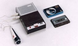
You've taken me back to my childhood. My parents had one of these:...and the chassis will have a DIN.
Attachments
Member
Joined 2009
Paid Member
I do like the idea of single ended Class A if we are to include a headphone amplifier. Did you or somebody you know, get a chance to listen to this circuit through headphones ?Here is a bit of fun I did with a NE5532 in SE class A. The idea was to drive headphones ...
The amplifier that got me thinking about this type of topology is called the SEWA and was published over in the Pass forum a few years ago.
http://www.diyaudio.com/forums/pass-labs/66822-sewa-seven-watt-amplifier.html
One guy built a whole stack of amplifiers and published the following impressions of it:
"The serious amps:
-Hiraga Le Monster: very nice and strong sound, but nothing special, if not that: You can not believe how can this 8 watt amp to be so strong!
-JLH1969: this is really a very good sounding amp! A reference amp for ever. Very musical sound, one of the best.
-ZEN "classic": nice and very pleasant sound for the ears, but the bass, dynamic, details, soundstage imagineing not so perfect than the ....... see later
ZEN-ZV4: nice and very strong and dynamic sound, but also not perfect like the ......
ZEN-BALANCED 25Watt: nice and brutal strong dynamic and bass etc.. sound! A bit "dark" or sound gloomy. I am afraid I prefer the 2nd harmonic distorsions more ....
Zen-Lite: It is a really nice sounding amp, almost perfect, but the details and the sound stage imagineing and the bass control are not so fine than the ....... see later
-Aleph5: very nice tube like sound with brutal power and dynamic.
SEWA-V1: OK here comes the winner! Nice, soft, warm etc. sound, but the most important what makes this amp unambiguous better than the others are the very strong and really (!) Detailed, controlled bass, mega-brutal dynamic, incredible micro fine details and excellent 3D sound stage. The music simply alive in the listening room!
I have never listened or felt such a presence good feeling! "
Now, who wouldn't want to scale that down for a nice headphone amplifier !?
Exactly! and that is why I ran the simulation of the diamond buffer (I will label the boosted supply version as the SLDB = super-linear-diamond-buffer) at 20kHz with 10V swing.The amp is then subjected to the highest voltage AND the highest frequency of that combined set of tones.
I wish we had good spice models for opamps such that we can make a good amplifier out of it.
It's become a known problem in some circles that it's hard to properly simulate a new design based on multiple i.c.'s resulting in board re-spins because the Spice models provided by manufacturers are too limited and they are hell-bent on protecting their IP so the detail is not there.Yes @ dedegogo. Designing with an op-amp is tricky because you don't really know what is inside it.
Last edited:
https://www.tubecad.com/2012/09/blog0244.htm
This is a good read on the Diamond and how to get more from it. Thank goodness he gives graphs of distortion. These ones look ideal. The Mighty diamond looks good. As he says, what good is a buffer that is shy about giving current. To be honest if you don't go for a real buffer then best not have one.
I think the ability to drive headphones is what you want, it's also a free lunch. It means never having doubts about any new idea that you want to try. One of my nicest amps had a 75R inverting input. My headphone cum preamp example designs would laugh at 75R.
Seeing as this Diamond Buffer looks a winner why not tweak the gain for the NAP140 clone amp to suit? If you make it 500 mV it should be OK. You might be able to usefully reduce Cdom as a result. That should give you identical HF distortion if the Cdom tweaked. A tiny tad more hiss doubtless if more sensetive ( ear to speaker type ). Quad were often told they shouldn't have 500 mV sensetivity on the 405. I think they got it right. That means at worse a 200 gain for the phono which is very OK. Personally I would use 12 + 17 for that with an option to have 62+17. The 62 being MC and 75 uS, the 17 is 3180/318 ( gain 160 ish at 20 Hz ). My brother who had years of experiance fixing amps thought 17 for the 1kHz 3180/318 was the ones that sounded best. He was a very scientific thinker, this was one of his rare rules of thumb.
Here is something very wrong that mostly works. The TL074 has a primitive protection circuit which is more or less a resistor like the Naim NAP although in a few 100's of ohms. Being JFET it will tollerate sharing the gain resistors and will not change much if a feedback cap added. LM324 and MC33079 were not happy in this circuit. If you notice 1.7V rms into 32R = 53mA which is ball park the same as my SE class A. As you can also see distortion is OK, but not preamp class. All the same of you have a TL074 in the junk box and want to drive some headphones cheaply it's going to be OK. MC33078 and BC337 eats it for breakfast and is less complex if trying to make one MC33079 do the same job. The TL074 ran for hours on this test without harm. It's just signal to + input with one resistor to 0V and all -ve common with gain feedback as per one TL071. Sorry if hard to follow. If ever a circuit could be Dead Bug it's this one.
@Gareth
Well the simplest is reported as the best. This is expected because complexity without appropriate refinement will produce undesirable side effects. My idea to use an IC diamond buffer (with no internal nfb loops) intends to address this. If you choose discrete, I recommend very simple and BJTs in current gain mode where possible, like the NAC. Or do some JFET trickery a la Curl if you are in an artisan mood.
Well the simplest is reported as the best. This is expected because complexity without appropriate refinement will produce undesirable side effects. My idea to use an IC diamond buffer (with no internal nfb loops) intends to address this. If you choose discrete, I recommend very simple and BJTs in current gain mode where possible, like the NAC. Or do some JFET trickery a la Curl if you are in an artisan mood.
Member
Joined 2009
Paid Member
I think I'll look at the feasibility of fitting all that I've earmarked for Board-1 onto a pcb within the constraints of my free layout software. I'll start out all-discrete as this is the worse-case for layout space and see how this influences choices. If I use the buffer on Board-1 for a headphone output I'll not have any gain so I was thinking any headphone outputs would go on Board-2. However, my experience with headphones is that gain is NOT required, line-level signals are plenty loud enough and the headphone output just needs some current drive capability.
In general, I read that gain is not needed in a modern pre-amp providing the output from the RIAA stage is high-enough (which will be the case here). However, adding the Naim gain amp on one of the boards will allow me to 'hear' how it sounds and that is of interest to me.
Any thoughts on the use of a single ended discrete single FET output for a headphone amp - not only based on the SEWA amp I posted above but I see many other examples around the forum and on the internet. They tend to have that favoured harmonic distortion profile rather than being ultra-low distortion.
Nigel - can we tweak the gain of the power amp without changing the sound signature away from the 'Naim' ? Reducing the sensitivity makes sense with a pre-amp with some gain. Increasing sensitivity removes all need for gain in the pre-amp but reduces the feedback factor in the power amp and increases distortion which may not be desirable. It may in fact be a more interesting idea to reduce the amplifier sensitivity and get a bit more distortion reduction from the negative feedback.
Last edited:
Member
Joined 2009
Paid Member
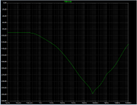
A Zener diode shunt has rather anemic regulation due to its high dynamic impedance
good comment Mark - although I will not use a simple zener regulator I will use a shunt regulator that uses a zener reference your post prompted me to look at the simulated dynamic impedance of the simple shunt regulator I was planning to re-use from my last attempt at a pre-amp attempt. In it's simple form it has an 'output' impedance of 1/4 ohm which I feel is too high when several circuits will be hanging off the same rails. Adding another BJT stage to the design pulls this impedance down to around 15m ohm which I think will be sufficient.
- Status
- Not open for further replies.
- Home
- Source & Line
- Analog Line Level
- TGMC - a modular control pre-amplifier