Member
Joined 2009
Paid Member
Member
Joined 2009
Paid Member
It feels like a good time to get started on the First Module
Some more thoughts: I'm thinking that my modular concept will play out like this:
Board 1 - will be a complete but minimal pre-amp that I can build and test and even start using as-is. This board will be mounted at the rear panel and will contain the MM phono stage, relay input switches, shunt regulator for everything on the pcb, a unity gain output buffer and on-board RCA connectors (phono, line 1, line 2, out). The control switches and volume potentiometer will be off-board, on the front panel. I think these functions are relatively low risk to design without prototyping first and I can start the schematic design and layout as soon as I get back from the business trip I'm on.
Board 2 - can be added after the first board is debugged and working. This board will be mounted at the front panel and contains all the other 'stuff' including control switches, gain stage, h.f. filter, possible head-phone output, LDR attenuator option etc.
Board 3 - maybe not a pcb but hardwired, think of it as a reserved space in the middle of the chassis between the first two boards for including something fun like a vacuum tube gain stage option.
How does this sound ??
Last edited:
Board 3 with the gain stage should be at the input before board1.
Activate this gain stage ONLY for those inputs that have too low an input level for the listening needs.
Activate this gain stage ONLY for those inputs that have too low an input level for the listening needs.
I built an amplifier years ago that has the same level of gain as your project Naim however my needs were also to cover use of another amplifier with about half that figure. My line stage has a gain of 2 to compensate for the difference. This precedes the volume control so there is a little attenuation of the CD input.
There seems to be some noticeable variation in CD recording levels of some of my CD's even between tracks on compilation ones. This can be annoying and eventually I built a remote volume control.
Mine has been a work in progress project which started with 3 small hobbyist matrix boards which were convenient for using IC's. I used separate boards for RIAA, Line, and input selection and devised a layout for LM317 and LM337 regulators on a separate pcb.
I replaced that pcb a year or two ago with a circuit based around a dual audio quality IC op. amp. I did a new pcb and and other power supply upgrades.
LM317 and LM337 regulators still form the heart of the regulated power supply for my low gain power amplifier - these and the transformer and capacitors are housed in a separate case from the power and preamp. The three cases are connected by umbilical cords and the preamp regulators are derived from the regulated supply for the power amplifier.
Earlier I suggested the use of a dual op.amp as a buffer for each signal input - the idea being to set the gain for these according to the level of input (and individual bandwidths) so all levels can be matched. I would put 1k output resistors at outputs of the IC's and short the outputs to earth for non - selected inputs.
While this can be done with relays I have often seen this being done using FET's or MOSFET's under logic control.
That may seem to be a sacrilege however in the long term how long do relay contacts remain free from airborne contaminants in a domestic environment - unless one buys those expensive types filled with inert gas.
One Naim concept you could consider is the use of mother boards into which you can plug in whatever boards you may wish to consider to allow for future upgrades and allowing for dual supply rails.
If you intend sticking with the Naim style of pre-amp the RIAA stage does not have enough gain to live with a line amplifier with unity gain or a gain of 2.
I think IC op.amps are fine at this level of amplification but you would be better to go discrete for higher gain levels that these.
You can double the supply. One way is a capacitor input Cockcroft Walton type idea. Sometimes you have to use a tripler as the ripple is large. Then the regulator can really earn it's living.
🙂Board 3 with the gain stage should be at the input before board1.
Activate this gain stage ONLY for those inputs that have too low an input level for the listening needs.
Interesting stuff about exotic capacitors: Humble Homemade Hifi - Cap Test
Some practical stuff here about choosing part values and tolerances for an RIAA filter: http://audio.engineeringvista.com/AudioKits/Phono-1/Design/index.htm
Some practical stuff here about choosing part values and tolerances for an RIAA filter: http://audio.engineeringvista.com/AudioKits/Phono-1/Design/index.htm
Last edited:
https://books.google.co.uk/books?id...transistor current source for valves&f=false
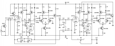
Hope this link works. Getting 7 V pk/pk with gain of 100 from 150VDC and only 0.04% THD . ECC83 ( page 142/143 ). MPSA92 CCS.
Morgan Jones my hero.
Hope this link works. Getting 7 V pk/pk with gain of 100 from 150VDC and only 0.04% THD . ECC83 ( page 142/143 ). MPSA92 CCS.
Morgan Jones my hero.
Theory of cartridge loading: Hagerman Technology LLC: Cartridge Loading
You have to choose whether or not to include circuitry for moving coil cartridges. They need more gain and less load resistance. OR you can buy external step-up transformers that go in-line with the turntable cables to approximately match a MC cartridge to a MM phono stage.
It might be an idea on your phono stage(s) to have a means to swap in load caps and resistors to tune it for the specific cartridge you will be using.
Note also that cartridges can produce a lot of ultrasonic energy and you want to take care in your pre to kill this off before it gets to your Naim amp (or any other amp for that matter - unless you are trying to impress your pet bat).
Last edited:
I think also have that HF roll off to be more like the Naim sound. I thought a passive RC filter after the buffer should be OK. If used with a Quad 405 it could be changed.
The MC33079 is good enough on noise for most MC. Even the Ortofon SPU at about - 64 dB typical. That's not too bad. You might do better by banking them in paralell. With a DL110 it is nearly silent.
The idea of the MC33079 is cheap, easy and hard to beat. Slightly valve like.
The MC33079 is good enough on noise for most MC. Even the Ortofon SPU at about - 64 dB typical. That's not too bad. You might do better by banking them in paralell. With a DL110 it is nearly silent.
The idea of the MC33079 is cheap, easy and hard to beat. Slightly valve like.
The thing is....CDs roll off pretty darned fast at 22kHz. If it were the case that an early roll-off causes a more Naim'ish sound then wouldn't a corollary be that CD sources make amplifiers sound more Naim'ish?
Member
Joined 2009
Paid Member
I plan to use solid state relays. They require only low current, have low parasitic capacitance (low cross-talk), are small and unlike mechanical relays they do not produce switching spikes on the power supply rails. There are no contacts to corrode or bounce. They are available cheaply in small packages and are ideal for small signal switching.While this can be done with relays I have often seen this being done using FET's or MOSFET's under logic control.
I thought about this and decided against it. That I use free pcb layout software that is limited to small board sizes doesn't help, but I would rather not have these card-edge connectors. I want the boards to lie flat now too so that I can use pcb-mounted RCA connectors along one side of the board.One Naim concept you could consider is the use of mother boards into which you can plug in whatever boards you may wish to consider to allow for future upgrades and allowing for dual supply rails.
No, I will use the NAD3020 RIAA stage instead of the Naim. It can provide 1V output with 5mV input with appropriate resistor values. It has very low distortion, very good headroom and is relatively simple. It's main shortcoming is that it is capacitor coupled despite being a dual rail design.If you intend sticking with the Naim style of pre-amp the RIAA stage does not have enough gain to live with a line amplifier with unity gain or a gain of 2.
On the first module, that I have referred to as 'Board 1' my plan is to go discrete (except for the solid state relays).I think IC op.amps are fine at this level of amplification but you would be better to go discrete for higher gain levels that these.
Last edited:
Member
Joined 2009
Paid Member
Board 3 with the gain stage should be at the input before board1.
Activate this gain stage ONLY for those inputs that have too low an input level for the listening needs.
I'd like to put the gain stage after source select and before the volume control. That seems to be the traditional location for it. Having it separate from Board 1 isn't a limitation in this regard and there simply isn't room to accommodate a tube gain stage onto Board 1 even if I wanted it there.
Last edited:
Member
Joined 2009
Paid Member
There's very little chance I'll move to an MC cartridge. That would imply that I have given up finding a sound I like with MM cartridges. My current TT isn't that hi-end either and I don't have very much vinyl. If I'm honest, the only reasons to include MC would be a) intellectual curiosity, b) to provide the capability should somebody else want to build my design. Both are unlikely so I don't either reason is enough justification to include it. The need for high gain with very low noise presents an interesting design challenge but it can't easily be tested out (no access to MC set-up) and will take up pcb layout space. I will stick to the idea that 'Board 1' should be designed without prototyping (should be low risk proven circuits) and provide the minimal functions needed to give me a basic pre-amp before I add further boards with circuits that may need to be prototyped first.You have to choose whether or not to include circuitry for moving coil cartridges. They need more gain and less load resistance. OR you can buy external step-up transformers that go in-line with the turntable cables to approximately match a MC cartridge to a MM phono stage.
I was thinking of dip switches for selectable load.It might be an idea on your phono stage(s) to have a means to swap in load caps and resistors to tune it for the specific cartridge you will be using.
An h.f. filter is easy to incorporate.Note also that cartridges can produce a lot of ultrasonic energy and you want to take care in your pre to kill this off before it gets to your Naim amp (or any other amp for that matter - unless you are trying to impress your pet bat).
Last edited:
I was thinking how I would do the switching. After many years of doing repairs I have had the chance of trying most things. The cheapest switch of all seems to me the best. That is the Lorlin ones. Take one apart to see the care in the design. It's feel and general performance can be enhanced by fitting long bushed rods to it.
No one seems to have taken any notice of my switched grounds idea. Let me tell you it is the largest hi fi upgrade that exists in this world bar none. If you like the DIN socket also should be thought better also, Vereker was 100% right to think that although BNC for the phono is good. How I do mine to say it again is 4 position, 3 way make before brake. One input is on a further 4,3 switch for not so important inputs ( I think it sounds no worse ). I use DIN where I can. I also use high grade 0.15 mm silver plated solid core between the sections where I can. The wire simplified the use of new layout should I need it. It is totally satisfactory. It was done that way as I found some parts and thought why not. For the first time ever I had very low hum. Ironicaly the modern gear is worse on that.
Thinking how I would improve this. If you use WD40 the Lorlin switch can live 10 years or more. It seems to have a bad week after it's been cleaned. Same with old switches in equipment. All the same WD40 woks best ( Mr Popple of Quad told me, better than posh cleaners ). My idea would be to have a 2 way 6 pole make before brake. Although FET switching is OK I would prefer relays. They can give > 50 000 switchings. Put them as far up the preamp as you can to get healthy current through them.
Here is the best bit. All the groups of 3 relays need is a DC feed. Stereo is not important. One DC feed will do all. The make before brake function will be retained in the relays ( a capacitor to each relay triple perhaps to ensure it ). The spare section of switch can do buffer gain via extra relays. You might need 30 relays. If bought carefully the price should be OK.
Looking at the NAD phono it seems to be all active ( ?? ) . In the day pasive 75 uS followed by active 3180/318 was liked. The 75 uS can also be the MC gain stage. If so make the 3180/318 about gain of 17 @ 1kHz. Some add a passive 2 uS after the active satge, mine is 200R + 10 nF ( makes scratches sound nicer and mimics fully passive, double inverting designs may not need it even if fully active ). This also prevents PSU hum loops and helps stability.
EC2-12SNU KEMET, Signal Relay, DPDT, 12 VDC, 2 A, EC2 Series, Through Hole, Latching Single Coil | Farnell element14
Gareth, what if you make the RIAA section a piggy-back board?
Then you decouple the more malleable phono circuit from the more permanent control section? Others could then use your pcbs and make their own add-on phono cards.
You might have already covered this...I haven't read the whole thread.
Then you decouple the more malleable phono circuit from the more permanent control section? Others could then use your pcbs and make their own add-on phono cards.
You might have already covered this...I haven't read the whole thread.
Member
Joined 2009
Paid Member
Good suggestions guys, I'd like to do the switched grounds and the chassis will have a DIN. There can be the possibility to add alternative phono input (need to think about the switching).
I looked at the NAD3020 service manual on Hi-Fi Engine and notice the RIAA and line stages operate from supply rails of +29.6 and -25.6 volts.
If you intend that the preamp is able to be upgraded the choice for the new circuit is likely to use different voltages. If you intend to use a different line stage to that for the NAD you would need separate regulators to meet that need anyway. It would not be a bad idea to double up on regulators at this stage.
To provide more adaptability for a duo it may be worth considering the provision of resistors for other voltage outputs connecting to a header strip so moving a jumper can change the settings.
A need for lower supply rails could be to use the NAD scheme as a pre-regulator and derive lower +/- voltages from this.
With regard to alternative phono input do you mean moving coil cartridge input. If so the simplest approach is to find a suitable circuit that is good enough and only requires some resistor values to be switchable.
The low input voltage of a moving coil does not require supply high supply rails - lower rails can have advantages in operating different transistors in a range where they produce less noise.
While the NAD may be a good RIAA stage for moving magnet there are other circuits that you could investigate if one stage is to cover dual needs.
Member
Joined 2009
Paid Member
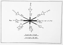
Star Signal (in addition to Star Ground)
Hopefully this sketch better explains how I plan to allow my modular approach to be easily expanded on. It's based on the idea of a Star Signal rather akin to the Star Ground concept. In this case, there is a node where the signal is common to the majority of the pre-amp functional circuits. Any circuits designed to modify the signal can simply tether themselves to the Star Signal point and 'do their thing'. The output buffer 'samples' the signal at the Star Signal point and 'serves' it to the power amplifier. This topology is in contrast to daisy-chainging the different functions where the signal is 'acted on' by various circuits in series as the signal travels from input to output. In the Star Signal approach, the circuits 'acting on' the signal operate in parallel instead.
The volume control in this approach is a variable shunt attenuator.
So anybody wanting to add an MC phono could make up a board with local regulator, MC phono amplifier, a relay to allow the input selector to enable / disable this source and a series resistor at the output which is then connected to the Star Signal. When the input select enables this input, it disables the other inputs. Any number of inputs may be added in this fashion.
Adding in a passive h.f. filter could be as simple as hanging a small capacitor off the Signal Star point. Or it could be a more sophisticated filter (operating in shunt mode).
Although I'm not going to implement this approach in the simple strictest sense shown in the sketch it does illustrate how the overall architecture is infinitely expandable. Clearly, we don't have to squeeze everything on the first p.c.b. My plan is to design 'Board 1' to include the NAD MM phono amplifier without provision for an MC amplifier.
Attachments
Last edited:
- Status
- Not open for further replies.
- Home
- Source & Line
- Analog Line Level
- TGMC - a modular control pre-amplifier