Member
Joined 2009
Paid Member
I used to think TH was easier to remove but that was when I made my own boards which were single sided without plated through holes. Trying to get leads out of double sided boards with plated through holes and then new ones back in again is a royal pain that has likewise, convinced me of the convenience of SMT. However, I'm still using two irons !
Bigun, any further updates? I took TGM8 (2-pole comp & Q3) to my dad's house yesterday to try it on one of his loudspeakers. We listened for over 90 minutes and both agreed it sounded superb in all its monaural glory. So much so he wants me to build one for him to replace his Marantz.
Ooops, I hope he will forgive the typo. No immediate plans to re-spin the board unless somebody asks.
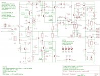
I've corrected it in the schematic at least, shows current as-built status.
Hi,
It is nice innovative artwork, and looks like sounds very good.
What I am wander about is protection circuit. Have you tested it? Something is not clear to me.
There is no difference between published ESP P3A and actual pcb schematic. PSRR comparison is possible using simulation.
I think that one worthwhile improvement would be to use simple cap multiplier on the pcb for VAS and input stage. Example on the schematic of Bora's Studio SE.
Bigun, can you publish corrected schematic for "simple basic" TGM8, one without enhanced VAS?
I think that one worthwhile improvement would be to use simple cap multiplier on the pcb for VAS and input stage. Example on the schematic of Bora's Studio SE.
Bigun, can you publish corrected schematic for "simple basic" TGM8, one without enhanced VAS?
Attachments
Member
Joined 2009
Paid Member
Hi,
I am wander about is protection circuit. Have you tested it? Something is not clear to me.
Hi overallfeedback,
You are right that the protection circuit hasn't been fully tested yet, but we have quite a few positive indications so far that it works as planned. Note that I did publish some new resistor values (post #245) and the LED needs to be taken off-board to make it work as intended. What we know so far:
a) The circuit does turn on and connect the speakers so we know the solid state relay works. It doesn't audibly distort the sound when the ss relay is 'closed' so we know the quality is good
b) There is no sound when the SS relay is 'open' so we know it is capable of protecting the speaker if it is triggered properly
c) There is a delayed turn on when you first power-up the amplifier, the indicator LED is initially Red and then turns Green. It happens fairly quickly, consistent with the simulated time (R36 & C20) plus I don't believe anybody has heard a turn-on thump. So we are pretty sure the delayed turn-on works.
d) I blew a resistor (R18) when the amp was powered up, which resulted in a fault condition that put the -ve supply rail voltage on the amplifier output. There was only a small thump in the speaker and the LED was Red and the speaker was disconnected. So we know the protection works with a large -ve dc-voltage fault on the output and we know it works fast enough.
I haven't tested the circuit with +ve dc-fault or for nuisance tripping yet.
Last edited:
Member
Joined 2009
Paid Member
Hi,I think that one worthwhile improvement would be to use simple cap multiplier on the pcb for VAS and input stage.
I've never used a cap multiplier on the front end of an amp before. I see it being used by others though and I trust it would work as advertised. I can look at including it on the pcb if you want to make a new pcb ???
I've made a 'basic simple' schematic - although some things may still change I think it captures what has been learned so far. Is this what you need ?can you publish corrected schematic for "simple basic" TGM8, one without enhanced VAS?
Attachments
Member
Joined 2009
Paid Member
PSRR comparison is possible using simulation.
Probably true up to a point, but the results of the simulation do depend on the device models being accurate and they do not allow for capacitive and inductive coupling from the power supply into the circuit as well as a host of other parasitics. I assumed 'perfect' passive components in the simulation too.
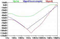
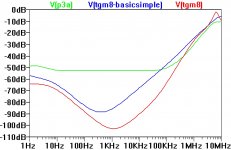
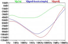
Here are my simulation results (attached). I removed all rail caps, just left 100nF rail decoupling in place. This allows a better comparison between amplifiers. All at +/-41V rails too. I used R18 of 560R and C8 of 220uF. Higher values of C8 will improve PSRR at low frequencies for the +Ve rail.
There are 3 plots, one for 'noise' on +Ve rail only (left plot), one for -Ve rail only (centre plot) and one for both rails simultaneously (right plot).
No wonder the P3a sounds better with MrEvil's regulator. But does TGM8 sound better with MrEvil's regulator ?
Attachments
Last edited:
No need to make a new pcb with cap multiplier for the front end. Just an idea.
Yes, that's the schematic that I need, one with changed resistor values to allow proper offset setting.
Yes, that's the schematic that I need, one with changed resistor values to allow proper offset setting.
Member
Joined 2009
Paid Member
Well it is a good idea but maybe not worth a new pcb.
For your build I can double check part values by simulation for your specific power supply voltages if you like?
You might like to see if R9 makes a difference. Rod uses 560R but I think you can go up to 1k too. The lower value gives more current through the input device and so a bit more slew rate (current is needed to drive the compensation capacitance) but higher value gives a little more gain & linearity. The difference may not be audible.
ivanlukic, are you also building one of these? It would be great if you are.
I'm using those values with +-40VDC and it works well. I've also "tested" that the speaker protection works properly: I accidently shorted the input to ground and the LED immediately turned red. I measured -11VDC before the n-fets and ~0VDC after - so its doing its job.
I'm using those values with +-40VDC and it works well. I've also "tested" that the speaker protection works properly: I accidently shorted the input to ground and the LED immediately turned red. I measured -11VDC before the n-fets and ~0VDC after - so its doing its job.
Member
Joined 2009
Paid Member
Hi Ivanlukic,
I'm not sure you will get the voltage you think from that transformer ? 25a.c. x sqrt(2) - 1.4 (two diode drops) = 34V with infinite capacitor, but realistically less than this. However, you can still use it for the amplifier.
I've installed four 4,700uF 50V (63V surge) Cornell Dubilier Electronics caps into the pcb and I'm trying to put together a lash-up of parts to make a regular power supply.
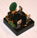
Photo shows a 35A bridge rectifier (cheap) with some 10nF ceramic capacitors (found in junk box) soldered between each connector. Then I added a 0R47 resistor in series with 470nF ceramic cap between the +ve and -ve pins. You need a hot iron for this as the pins suck heat away quite fast.
I'm not a big fan of wiring up the chassis and so doing a lash up now might be a good idea as it helps work out the wiring (and grounding) before I get some a new box for it. However, I managed to drop a hot blob of solder on my foot and my foot told me it was hot so I'm taking a break...!
I'm not sure you will get the voltage you think from that transformer ? 25a.c. x sqrt(2) - 1.4 (two diode drops) = 34V with infinite capacitor, but realistically less than this. However, you can still use it for the amplifier.
I've installed four 4,700uF 50V (63V surge) Cornell Dubilier Electronics caps into the pcb and I'm trying to put together a lash-up of parts to make a regular power supply.
Photo shows a 35A bridge rectifier (cheap) with some 10nF ceramic capacitors (found in junk box) soldered between each connector. Then I added a 0R47 resistor in series with 470nF ceramic cap between the +ve and -ve pins. You need a hot iron for this as the pins suck heat away quite fast.
I'm not a big fan of wiring up the chassis and so doing a lash up now might be a good idea as it helps work out the wiring (and grounding) before I get some a new box for it. However, I managed to drop a hot blob of solder on my foot and my foot told me it was hot so I'm taking a break...!
Attachments
Last edited:
Bigun, do you see any benefit increasing C8 & C9? Currently I have been using 100u here, but have some 470u Nichicon HE caps that will fit.
Member
Joined 2009
Paid Member
Theoretically a larger C8 will improve the -ve rail PSRR by extending the RC corner frequency to lower frequencies. I don't see any need for a larger C9. These caps do carry audio related signal currents so I ended up using 220uF Nichicon fine gold audio-grade caps - I can't tell you if they make a difference though as I didn't do any comparisons.
Good to know... I'll just stick with the 100u Nichicon HE caps since they have worked so well.
Have you tried wiring that rectifier block up directly to your board with the 4x 4700u CDE caps? It will be a few days until my parts arrive, and I am very keen to know whether the onboard bank direct to rectifier is a go / no-go.
Have you tried wiring that rectifier block up directly to your board with the 4x 4700u CDE caps? It will be a few days until my parts arrive, and I am very keen to know whether the onboard bank direct to rectifier is a go / no-go.
Member
Joined 2009
Paid Member
I am very keen to know whether the onboard bank direct to rectifier is a go / no-go.
oh, it's a GO baby, it's a go ... 😀
With no input the speaker is silent. There is NO hum, nada. I tried to hear the base noise level of the amp and I can just make something out in the upper mids, maybe, with my ear pressed up by the cones. It's quiet.
At least it was quiet, it's playing pretty loudly now !
Still stuck with iPad input, haven't made a volume control yet. I measured the ripple at the +Ve supply rail, after the filter caps (no load), at about 40mV. I'm using an EI transformer pulled out of an old Fisher amp which gives me around 42V rails. Strangely the quick speaker disconnect isn't doing what it should, the LED stays green until it's last breath. On the scope there is no turn of thump and in practice I haven't heard one either so it isn't an issue but I will try to understand what is going on all the same as I may want to use this circuit again in the future.
Last edited:
BRILLIANT!!!
Did you install the 0R33 resistors in the PSU? If you did, this could explain why my simple "4700uf per rail" supply had some noise on it?
Did you install the 0R33 resistors in the PSU? If you did, this could explain why my simple "4700uf per rail" supply had some noise on it?
Member
Joined 2009
Paid Member
Yes, I installed the 0R33 on the pcb so as to make the CRC. But I think the other components I mounted on the rectifier are also important.
Another factor affecting higher frequency noise is how clean your mains is and how much of it gets through your transformer. An EI transformer has less inter-winding capacitance than a toroid, unless the toroid has a shield between the windings.
Of course you also need to avoid hum by using proper grounding. I used a pair of diodes wired in parallel but facing opposite directions to isolate the amplifier star ground from the temporary chassis which my safety earth is connected to.
Last edited:
Very pleased to hear that!! It means I can forgo the off board caps and keep the wiring minimal.
I also isolate my star ground from chassis ground (safety ground) the same way you describe, except I run it through a 35A bridge rectifier, with the 10R 5W resistor and 100n ceramic wired across the terminals, per the write up on Rod Elliott's page here:
Earthing (Grounding) Your Hi-Fi - Tricks and Techniques
I suppose it is wasteful to use a 35A bridge in this way, but I find it very convenient to have something that bolts to the chassis, that I can hang the components off, and will accept fast on connectors.
In all testing I've been using E-I transformers salvaged from old amps.
I'll wire up my bridge rectifier as you have described. Is the value of the snubbers important? Will 100n ceramics do the job just as well?
Member
Joined 2009
Paid Member
- Home
- Amplifiers
- Solid State
- TGM8 - my best amplifier, incredible bass, clear highs, no fatigue (inspired by Rod Elliot P3a)