Member
Joined 2009
Paid Member
X7R is fine for this, but 100n is too small. You may not have anything suitable. I found I had a 4.7u in my junk box but I would have used 10uF or 22uF if I could have found one in chip form in my junk box. The zener has a low impedance so it needs to be bypassed by a fairly large cap.
From what I read a low esr NPO/CoG is not suitable for decoupling. Too much risk of instability.
The slightly lossy X7R seems to be ideal for decoupling and due to extremely low ESL works to even higher frequencies.
For HF noise filtering of a Zener, a smaller cap than 4u7F is still quite effective.
MLCC are available in smallish packages with enormous capacitance compared to older technologies.
Last edited:
Member
Joined 2009
Paid Member
For HF noise filtering of a Zener, a smaller cap than 4u7F is still quite effective.
Thanks Andrew - that's good to know !
Hello Bigun,
When I start the tgm8, the dc offset is 100 and than started to decrease until -10 mv about #1 minute. Stable 10 until -12 mv. Is it ok?
When I start the tgm8, the dc offset is 100 and than started to decrease until -10 mv about #1 minute. Stable 10 until -12 mv. Is it ok?
Member
Joined 2009
Paid Member
Hi Kdi,
Congrats on your first post to the forum !
I don't see any problem with your amplifier, initial offset of 100mV won't cause any problems and 10mV after 1 minute is very good.
You are seeing a bit more offset change during warm-up time than I remember seeing in my own tests so I'll look at my own next time I power it up.
Which version did you make, do you use the MOSFETs or only BJT ? do you have two-pole enhanced front end or did you use simple VAS ?
Can you post some photo of your construction ?
Member
Joined 2009
Paid Member
speaker protection and ss relay working fine !
I decided today that I would further investigate my concerns that the dc-protection circuit was not properly cutting-off the speakers when the power is removed from the amplifier. There is no concern about it working properly when there is a dc-offset error, the dc-protection has been seen to work very well when there is dc failure at the output. But I had hoped the circuit would also cut off the speakers quickly on power-off to avoid any power-down ‘noises’ that some amplifiers are known to make. My concerns on the quick disconnect functioning properly were because the indicator LED remained green whilst the rails collapsed instead of the LED turning off quickly.
So I built the 2nd channel of TGM8 without power devices installed (and set the bias to minimum so the drivers would not be active). Without power devices installed I could probe all the different points of the circuit more easily.
a) I measured the voltage across R41, the 10k base resistor to Q17. I measured around 9.5V which indicates R41 flows about 1mA with the power-on. On power off this voltage falls to 0.0mV within 3s. This is the correct behaviour, the zener diode is cutting off Q17’s base current when the rail voltage collapses below 30V or so.
b) I also measured the voltage across the collector-emitter of Q17. It shows only 50mV or so at power-on which indicates the device has a low resistance, i.e. it is turned ‘on’ and flowing current - which is the correct behaviour. At power-off this voltage increased to around 26V or so within 3s. This indicates it has become a high resistance, i.e. it has turned ‘off’ and is no longer flowing current - which is the correct behaviour.
c) I also measured the voltage output of the photovoltaic opto device that drives the gates of the solid state relay FETs. At power-on the opto developed just over 9V of gate drive voltage (nice!) and at power off it fell to 100mV or so within 3s which turns off the FETs. This is the correct behaviour.
So the circuit is working just fine but there is enough leakage current through the LED to produce a dim light. There is no problem after all, the speaker protection works, the speaker delayed turn-on is working and the speaker disconnect at power-off is also working.
Member
Joined 2009
Paid Member
[B]First Listening Tests[/B]
Source: I decided it was time to listen to the TGM8 with a better source. My CD player is a YBA unit and is the most expensive piece of hi-fi I own. It sounds remarkable. I was too lazy to wire up a volume control and right now I think I only have some dual pots pulled out of old Japanese mid-fi units from the e-waste. But I remembered that my Bryston BP60 integrated amplifier has separate pre-amp outputs. This unit is essentially a Bryston BP-20 preamp coupled to a Bryston 2B power amplifier. If you want to know if the Bryston is good enough to use for listening tests then you can read here: “The sound is...unimpeachable.” http://www.stereophile.com/content/bryston-b-60r-integrated-amplifier-page-2
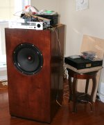
Speaker: I decided to use my Big’un speaker, something I built a couple of summers ago. This is an open baffle 15” single full-range driver with a cabinet inspired by the Yamamoto YS-500 http://www.6moons.com/audioreviews/yamamoto9/speaker.html.
Although it isn’t corrected for flat frequency response it is the daily-use speaker in my household for listening to music so we are all familiar enough with it to know if something playing through it sounds good or not. http://www.diyaudio.com/forums/full-range/217893-bigun-audio-nirvana-super-15-a.html
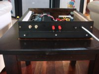
You can see my kludged set-up perched on top of the speaker cabinet !
Listening: The ‘first sound’ using my FM radio (whilst setting up the CD player) was that it sounded a bit ‘thin’ and not very clean. I’ve had this trouble with radio before, the sound quality is limited, not least from the excessive compression they apply to ‘pop’ music. So I moved on to hook up the CD player. There were no turn-on noises or turn-off noises. For CDs I chose 3 discs, i) a special edition Chesky ’10 Best’ from 2006 (Chesky is an excellent recording and mastering company), ii) Diana Krall ‘the girl in the other room’, and iii) Dusko Goykovich ‘Soul Connection’.
First off - It sounded top-notch straight from the get-go.
Bass: I noticed the bass first, it was the best I’ve heard from any of my amplifiers, both DIY and commercial. The Bryston 2B power amplifier has good bass, but the TGM8 is more solid, tighter and just as deep. My young son, who plays the piano noticed the quality of the bass immediately.
Mids: The sound was clean top-to-bottom. I must admit that I am used to a bit more richness in the mids, the TGM8 doesn’t sound clinical by any means but the mids are neutral without any added ‘richness’ or ‘liveliness’. I have made amplifiers that have intentional ‘voicing’ or distortion (the first TGM) which sounds richer, more laid back, the “ 70’s “ sound if you will. The TGM8 mids don’t have that sound, it is simply ‘honest’.
Treble: There are two things I listen for, one is wire brushes & drum sticks on cymbals, the other is irritation. The cymbals were clear, neither splashy or etched. There was no artificial ‘sparkle’.
I may have damaged my ears with loud music a decade ago and find that some amplifiers/speakers give me hyperacusis. If an amplifier/speaker is going to irritate my ears I usually know straight away. With the TGM8 I didn’t detect any irritation at all. The treble gets a strong 'thumbs-up'.
Voices: Sounded natural, no evidence of ‘ssssss’ when listening to Diana Krall (although sibilance is not something she’s ever been acused of!)
The trumpet by Dusko Goykovich was a very good test. I didn’t have any good trumpet in my collection before and this instrument covers a good range of frequencies from upper mids to the treble - and with gusto. On the TGM8 it sounds very clear and very powerful - it was energizing.
I switched over to the Bryston 2B amplifier. It sounded fine, its a great amp, but I felt a desire to switch-back to the TGM8 😀
More listening will be needed, this is all just first impressions. By the way, I attended a live orchestral concert last night (Haochen Zhang, piano - my gosh can this guy play!) so my ears have a recent memory of live music and I didn’t hear any weaknesses from the TGM8 today.
Source: I decided it was time to listen to the TGM8 with a better source. My CD player is a YBA unit and is the most expensive piece of hi-fi I own. It sounds remarkable. I was too lazy to wire up a volume control and right now I think I only have some dual pots pulled out of old Japanese mid-fi units from the e-waste. But I remembered that my Bryston BP60 integrated amplifier has separate pre-amp outputs. This unit is essentially a Bryston BP-20 preamp coupled to a Bryston 2B power amplifier. If you want to know if the Bryston is good enough to use for listening tests then you can read here: “The sound is...unimpeachable.” http://www.stereophile.com/content/bryston-b-60r-integrated-amplifier-page-2
Speaker: I decided to use my Big’un speaker, something I built a couple of summers ago. This is an open baffle 15” single full-range driver with a cabinet inspired by the Yamamoto YS-500 http://www.6moons.com/audioreviews/yamamoto9/speaker.html.
Although it isn’t corrected for flat frequency response it is the daily-use speaker in my household for listening to music so we are all familiar enough with it to know if something playing through it sounds good or not. http://www.diyaudio.com/forums/full-range/217893-bigun-audio-nirvana-super-15-a.html
You can see my kludged set-up perched on top of the speaker cabinet !
Listening: The ‘first sound’ using my FM radio (whilst setting up the CD player) was that it sounded a bit ‘thin’ and not very clean. I’ve had this trouble with radio before, the sound quality is limited, not least from the excessive compression they apply to ‘pop’ music. So I moved on to hook up the CD player. There were no turn-on noises or turn-off noises. For CDs I chose 3 discs, i) a special edition Chesky ’10 Best’ from 2006 (Chesky is an excellent recording and mastering company), ii) Diana Krall ‘the girl in the other room’, and iii) Dusko Goykovich ‘Soul Connection’.
First off - It sounded top-notch straight from the get-go.
Bass: I noticed the bass first, it was the best I’ve heard from any of my amplifiers, both DIY and commercial. The Bryston 2B power amplifier has good bass, but the TGM8 is more solid, tighter and just as deep. My young son, who plays the piano noticed the quality of the bass immediately.
Mids: The sound was clean top-to-bottom. I must admit that I am used to a bit more richness in the mids, the TGM8 doesn’t sound clinical by any means but the mids are neutral without any added ‘richness’ or ‘liveliness’. I have made amplifiers that have intentional ‘voicing’ or distortion (the first TGM) which sounds richer, more laid back, the “ 70’s “ sound if you will. The TGM8 mids don’t have that sound, it is simply ‘honest’.
Treble: There are two things I listen for, one is wire brushes & drum sticks on cymbals, the other is irritation. The cymbals were clear, neither splashy or etched. There was no artificial ‘sparkle’.
I may have damaged my ears with loud music a decade ago and find that some amplifiers/speakers give me hyperacusis. If an amplifier/speaker is going to irritate my ears I usually know straight away. With the TGM8 I didn’t detect any irritation at all. The treble gets a strong 'thumbs-up'.
Voices: Sounded natural, no evidence of ‘ssssss’ when listening to Diana Krall (although sibilance is not something she’s ever been acused of!)
The trumpet by Dusko Goykovich was a very good test. I didn’t have any good trumpet in my collection before and this instrument covers a good range of frequencies from upper mids to the treble - and with gusto. On the TGM8 it sounds very clear and very powerful - it was energizing.
I switched over to the Bryston 2B amplifier. It sounded fine, its a great amp, but I felt a desire to switch-back to the TGM8 😀
More listening will be needed, this is all just first impressions. By the way, I attended a live orchestral concert last night (Haochen Zhang, piano - my gosh can this guy play!) so my ears have a recent memory of live music and I didn’t hear any weaknesses from the TGM8 today.
Attachments
Last edited:
Member
Joined 2009
Paid Member
Have been listening all afternoon, mostly to Dusko. Tried swapping on a CD soundtrack from the movie Pulp Fiction and could immediately tell the recording quality was more of 'FM pop quality'. I not too long ago changed over to a CD by Madeleine Peyroux 'the half perfect world'. Just amazing to listen to - I can also say the TGM8 has full approval from my better half 😀
Hi Gareth,
So are you listening to this in stereo or mono? I only see one speaker. If in mono, how are you blending the stereo signal?
Thanks, Terry
So are you listening to this in stereo or mono? I only see one speaker. If in mono, how are you blending the stereo signal?
Thanks, Terry
Great listening notes and photo - an entertaining read!
To my ears it is the bass that impresses above all else: the potential was apparent from the first listening session in the workshop, with the amp plugged into an MP3 player and small bookshelf speaker. With a proper source and quality floorstanders the bass has weight, depth, whilst remaining composed during complex passages. I concur with your assessment.
Your comment about the (lack of) richness I find very interesting: in all my experimentations with the P3A I've regarded the sound as a little 'thin' in the midrange and bass. The TGM8 midrange is unembellished and so I would not characterise it as a 'rich' sound, but it does however have terrific body, weight and energy, that I've found lacking elsewhere. As I said earlier, VSSA midrange is similar in character, and I think that one has a little more detail and resolution.
The treble is smooth, refined, detailed, and a little laid back. It shares a lot in common with the P3A sound, which matches so well with the ribbon tweeters on my main loudspeakers, which can sound a little 'in your face' with some combinations.
Member
Joined 2009
Paid Member
Hi Terry,
Yes, it is mono. I find stereo requires a careful set-up with the speakers and listener and the room all being properly arranged. When done well it's very enjoyable as we all know. However, there are many (too many?) recordings where the stereo imaging has been manipulated during the mastering process and as a result it can often sound 'false' to my ears. Rather like some people don't like 3D movies and prefer to watch regular 2D movies instead. This stereo effect also varies between CDs, between songs being played on the radio - all because each recording studio did their 'own thing'. For regular listening I prefer mono. But for mono I find the open baffle speaker to be the best (so far) as it provides some ambience in the room. That big speaker sits in a place where the sound can spread out around the house and doesn't require a careful seating set-up as with stereo. When I had a stereo set up in the same location it never sounded right - the two sound sources were bouncing around too much. I didn't try to blend the source into two channels, I just used one channel. I'm sure that could be improved on. My FM radio has a mono-stereo switch for the purpose.
Last night, at the orchestra, I didn't find that I had much of a stereo sensation at all. The sound came from the direction of the orchestra but it also enveloped me because of the acoustics of the hall. It was all very natural and this is the experience I get with my open baffle speaker at home more than I had with stereo.
I will be building TGM8 as a stereo amplifier when the box arrives and I'll then try it in stereo mode - the wires are a bit messy to do that now. I have a nice pair of PMC floor standers in my basement that will provide a good stereo image.
Hi Christian,
It's good to hear your comparison with the P3a. I was too lazy to build the pcb into a p3a version (different parts and different values) so I didn't do the comparison myself. But I was motivated to design the TGM8 because of the extensive and consistent good reports about the P3a, including those of SAKIS who really knows that amp well. If TGM8 has, in your ears, retained the flavour and good features of the P3a and yet has surpassed it in some key areas - then I'm very happy because it means I succeeded in the very goal I set out at the start 😀
Last edited:
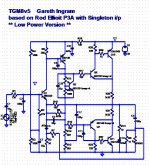
Retro Version !
I had taken the liberty of modifying the TGM8v5 as a possible retro (single PS) variant. I did not have sufficient knowledge to correct the Rs and Cs. Can you go through the scheme and offer corrections? Can the circuit around Q2 and Q3b be adopted for this version?
--gannaji
If I have time I'll consider it - feel free to remind me later. The first version though will be split rail, it's likely to be too difficult to accommodate both on the same pcb.
I had taken the liberty of modifying the TGM8v5 as a possible retro (single PS) variant. I did not have sufficient knowledge to correct the Rs and Cs. Can you go through the scheme and offer corrections? Can the circuit around Q2 and Q3b be adopted for this version?
--gannaji
Attachments
Last edited:
Member
Joined 2009
Paid Member
Hi, I'll take a look in more detail but first I am looking at your schematic - I think you have to be carefull about temperature drift of the dc-offset when using the Single device input - not sure how you're planning to do that with your simplified version - do you have something clever going on here... looks interesting.
Member
Joined 2009
Paid Member
An alternative fix for the solid state relay indicator LED
I decided to explore the option of fixing it so that the LED can be installed into the pcb instead of installing off-board with resistor from common cathode to the -ve supply.
The problem with the original circuit was a relatively small voltage drop across the LED inside the photovoltaic driver so that there wasn't enough voltage to light the indicator LED (green) if the common cathode was returned via R39 to ground. Earlier in the thread this issue was addressed by mounting the LED off-board and returning the common cathode to the -Ve rail with an external 82k resistor. This is fine if you want to install the diode in the front panel. I wanted the option of keeping it on the pcb. So I had to change the circuit to provide more voltage for the indicator LED. If I could install a diode in series with the photovoltaic's internal LED I could raise the total voltage drop available for the green indicator LED. I decided to install a common 1N4148 signal diode between the photovoltaic LED (pin 3) and ground. This meant surgery to the pcb.
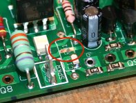
There is a trace on the top side of the pcb from pin 3 of the photovoltaic driver that runs under the power resistor R31 to ground (at the pin of C20). I removed R31 to gain access to the trace and used a small grinding bit in my Dremmel to remove the protective layer off a short section of that track and then to cut through the copper in order to make a break in the trace (1st image). I tinned the exposed bare copper with solder and then installed the diode (2nd image). Then I put back the power resistor (3rd image) which actually hides the whole thing - although I think it was neat enough.
I found by experiment that R39 should be in the range 560R to 1k2, with the lower value producing a brighter light from the green LED. I installed the LED into the pcb. It works fine. On power up it turns red momentarily and then green for normal operation. I did check to ensure that when it is green there is more than 9V at the output of the photovoltaic to power the gates of the solid state relay.
This edit is not necessary, it's purely optional. The circuit works fine without this edit but you either don't get the green LED lighting up (just the red half) or you have to mount it off-board.
I decided to explore the option of fixing it so that the LED can be installed into the pcb instead of installing off-board with resistor from common cathode to the -ve supply.
The problem with the original circuit was a relatively small voltage drop across the LED inside the photovoltaic driver so that there wasn't enough voltage to light the indicator LED (green) if the common cathode was returned via R39 to ground. Earlier in the thread this issue was addressed by mounting the LED off-board and returning the common cathode to the -Ve rail with an external 82k resistor. This is fine if you want to install the diode in the front panel. I wanted the option of keeping it on the pcb. So I had to change the circuit to provide more voltage for the indicator LED. If I could install a diode in series with the photovoltaic's internal LED I could raise the total voltage drop available for the green indicator LED. I decided to install a common 1N4148 signal diode between the photovoltaic LED (pin 3) and ground. This meant surgery to the pcb.
There is a trace on the top side of the pcb from pin 3 of the photovoltaic driver that runs under the power resistor R31 to ground (at the pin of C20). I removed R31 to gain access to the trace and used a small grinding bit in my Dremmel to remove the protective layer off a short section of that track and then to cut through the copper in order to make a break in the trace (1st image). I tinned the exposed bare copper with solder and then installed the diode (2nd image). Then I put back the power resistor (3rd image) which actually hides the whole thing - although I think it was neat enough.
I found by experiment that R39 should be in the range 560R to 1k2, with the lower value producing a brighter light from the green LED. I installed the LED into the pcb. It works fine. On power up it turns red momentarily and then green for normal operation. I did check to ensure that when it is green there is more than 9V at the output of the photovoltaic to power the gates of the solid state relay.
This edit is not necessary, it's purely optional. The circuit works fine without this edit but you either don't get the green LED lighting up (just the red half) or you have to mount it off-board.
Attachments


Last edited:
Member
Joined 2009
Paid Member
I had taken the liberty of modifying the TGM8v5 as a possible retro (single PS) variant. I did not have sufficient knowledge to correct the Rs and Cs. Can you go through the scheme and offer corrections? Can the circuit around Q2 and Q3b be adopted for this version?
--gannaji
Hi Gannaji,
I ran your simulation (R set to 100k - although I'm not sure you even need that resistor there at all) and I see it working fine. With the dc coupled output the thermal drift in the dc point of the output won't be an issue of course and you won't have to worry about dc offset damaging your speaker.
I would reduce the compensation capacitor (C6 in your simulation) - but do it once built so you can hear the change in sound. A value of 33pF may be fine for example.
For a first-cut I'd say you got it right, the values look good but some tweaks might help. The output cap would be best if you could enlarge to twice the capacitance as you want a low frequency cut off to reduce capacitor distortion in the bass - i.e. aim for 10,000uF at the output. You could increase R9 from 560R to 1k; this will increase open loop gain for a bit less distortion although it will have the side effect of reducing the current through the input device (but C6 can be much smaller so slew rate is still good). I would also change R14 and R15 to 2k2 to ensure better current flow through the VAS with your lower power supply voltage.
You may have a turn-on thump without any speaker delay circuit though. There may be a trick we can try - I will have to see if I can find it on the internet again (means adding a diode and resistor if I remember correctly).
Last edited:
I am trying to build a 5.1 home theater using P3A and P68. Can i use single 25-0-25 transformer for all P3a?
Yes you can. That voltage would gives you around 55W per channel into 8R. Just ensure it can deliver sufficient current to meet your power targets. For 5 channels of P3A I'd suggest at least 500VA.
For 6 channels of 55W each (total max = 330W), I'd suggest any transformer from 330VA to 660VA.
But will all six channels play very loud at the same time?
I suspect not quite. I suspect that a smaller transformer can do this duty. Maybe even as small as 200VA to 400VA.
But will all six channels play very loud at the same time?
I suspect not quite. I suspect that a smaller transformer can do this duty. Maybe even as small as 200VA to 400VA.
Thanks to you all, Already I have 300VA transformer. I want to use this transformer for 5 P3A channels. For P68 i am using 500VA. I will use this 5.1 home theater for watching movie. At the time of listening music i will use 2.1 only. So as per your statement 300VA(for 5 channel) and 500VA(for Sub woofer) will meet my requirement. I will never play this home theater very loudly. Thanks again for your kind reply.
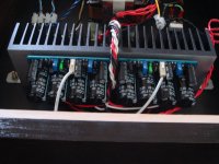
Hi All
I'm pleased to present my completed TGM8 stereo amp. This is my first attempt at building a case from scratch and easily consumed over 90% of the construction time. The chassis and back panel are sheet steel spray painted matt black, the other panels are Tasmanian Oak stained with two coats of Japanese Black.
I'm pleased to present my completed TGM8 stereo amp. This is my first attempt at building a case from scratch and easily consumed over 90% of the construction time. The chassis and back panel are sheet steel spray painted matt black, the other panels are Tasmanian Oak stained with two coats of Japanese Black.
Attachments


- Home
- Amplifiers
- Solid State
- TGM8 - my best amplifier, incredible bass, clear highs, no fatigue (inspired by Rod Elliot P3a)