MJL21193,
pretty nice design, but how do you explain the function of U21/22/27 and the position of the CCS formed by U23/26?
pretty nice design, but how do you explain the function of U21/22/27 and the position of the CCS formed by U23/26?
Member
Joined 2009
Paid Member
I looked at the data sheet for this bridge - no mention of soft-recovery. I may be overestimating the benefit of this feature and have zero experience in either case, but since I now have 25 of these diodes there's no turning back!
Yes, the LTP is certainly running lean. It's not that I'm excessively stubborn, but I see this as an adjustable item so my schematic doesn't imply that the final design will be that way. I still associate some of the 'black magic' of the final sonics to the way the LTP is set up.
I was hoping you wouldn't pick on C1, the pcb is squashed for space around there ! - for the HT application the DIY speakers will be set up with a -3dB at 80Hz - 100Hz will C1 get me down to 100Hz ?? somewhere I read that you need higher values if using electrolytic input caps (which I'm not) ??
Yes, most definitely plan to heatsink the VAS. I have a few options based on some heatsinks I've ripped off discarded circuit boards people threw out recently - worse case I'll screw on a simple piece of Al sheet and crinkle the edges.
I will have to check, but R3/30 partly helped, at the tim, with the pcb layout. As a fall back, I have some zero ohm resistors for camouflage !
R25/26 do need fixing don't they. Good thing I bought a 'selection pack' of resistors so that I can make last minute changes.
(I hope I remember to print out the PCB pattern in reverse)
And thanks for helping out, it makes all the difference.
Member
Joined 2009
Paid Member
Regarding your design, I like it. Beats mine for total devices, like TGM 2 on steroids.
Why no charge suckout caps on the output devices, can C5 cover this need ?
You have no bootstrap, VAS is linarized with additional devices. Why do you pick this option ?
Why no charge suckout caps on the output devices, can C5 cover this need ?
You have no bootstrap, VAS is linarized with additional devices. Why do you pick this option ?
...Linearity/accuracy is not the primary aim for me here but to sample the sound with some 2nd order harmonics from the imperfectly matched LTP...
I encountered the reason somewhere that circuit is made not balanced physically but is made balanced electronically meaning same amount of current should be passing on the EC of 2 input trannys for minimum distortion. Such case the value of resistors on input collector is important.
Regards,
mannycc
Lumba Ogir said:MJL21193,
pretty nice design, but how do you explain the function of U21/22/27 and the position of the CCS formed by U23/26?
Hi Lumba,
U21,U22 are CCS for the VAS (U13,U12) - U24, U25 are current mirror.
U27 is bias supply for U21, U22 CCS.
U23, U26 set voltage for cascoded VAS.
Bigun said:I looked at the data sheet for this bridge - no mention of soft-recovery. I may be overestimating the benefit of this feature and have zero experience in either case, but since I now have 25 of these diodes there's no turning back!
And thanks for helping out, it makes all the difference.
Hi Gareth,
I'm not a big believer in some of the more mystical aspects so the simple standard recovery bridge does me fine.
I have been where you are (still am, some would say 😀 ) and know the value of solid advise. Too often the new guy is left to take his lumps.
Bigun said:Why no charge suckout caps on the output devices, can C5 cover this need ?
You have no bootstrap, VAS is linarized with additional devices. Why do you pick this option ?
C5 is the "suckout" cap.
The design grew out of another, covered here.
It's still in the planning stage and has been stalled for several months. I'll finish it eventually I expect.
Member
Joined 2009
Paid Member
I'm not a big believer in some of the more mystical aspects
I shall be claiming superior sonics from these diodes and my special formula for the solder then
😀
Lumba Ogir said:MJL21193,
I see, however it`s not done correctly.
Hi Lumba,
Feel free to explain and elaborate here. Let's not gum up Gareth's thread with other issues.
Gareth,
Secret solder formula? Alchemy? 😀
Member
Joined 2009
Paid Member
mannycc said:
I encountered the reason somewhere that circuit is made not balanced physically but is made balanced electronically meaning same amount of current should be passing on the EC of 2 input trannys for minimum distortion. Such case the value of resistors on input collector is important.
Regards,
mannycc
That's correct, you have to look carefully at the current flow through each side of the LTP input stage rather than simply making each leg 'look' the same on the schematic. What I find helpful is the emitter degeneration resistors which in the SPICE simulation allow you to quickly compare the current flow balance by looking at the voltage drops across these two resistors.
I understand that these emitter degen resistors help with linearity, but not everyone likes them, fearing that they add noise.
Member
Joined 2009
Paid Member
Hi Gareth,
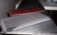
What are you using to cut it?
I've seen some really dangerous stuff here when it comes to cutting aluminum. One member lost the tips of 2 fingers and did severe nerve damage cutting aluminum on a tablesaw.
I do quite a bit of cutting aluminum, both in my line of work and in this hobby. Many here compare it to cutting wood, and though it is relatively soft and easy to cut, it has a way of sticking to blades and teeth that can cause it to bind and kick back. Not cool to interrupt a fine Sunday morning with a visit to the emergency room to have things sticked up (or worse).
Member
Joined 2009
Paid Member
No way I'm putting my nice new plywood finishing blade through this heatsink. I use a jigsaw, slowish but controlled.
Many years ago I put a high speed drill through my thumb. First off I thought I'd just knicked it, went to the sink to run it under the tap. Thing was, blood was flowing into the sink but the entrance wound was clear. After looking under my thumb and noticing the exit wound I realized what I'd done and promptly turned white - my sister had to quickly put a chair under me
Many years ago I put a high speed drill through my thumb. First off I thought I'd just knicked it, went to the sink to run it under the tap. Thing was, blood was flowing into the sink but the entrance wound was clear. After looking under my thumb and noticing the exit wound I realized what I'd done and promptly turned white - my sister had to quickly put a chair under me
Bigun said:No way I'm putting my nice new plywood finishing blade through this heatsink. I use a jigsaw, slowish but controlled.
Many years ago I put a high speed drill through my thumb.
Jigsaw

I've been a carpenter for nearly 25 years and had my share of mishaps, so I feel your pain. I still have all of my fingers though 😀
PS: I sent you an email.
Member
Joined 2009
Paid Member
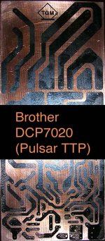
I don't know if this image is clear, but it is my 2nd attempt at toner transfer for making this pcb. If you can see what I can see (!) it's unsuitable for etching. The toner has poor coverage. It is stuck to the surface nicely and there's virtually no bits missing. Lots of pin holes.
I suspect that the issue is the toner. I'm using a Brother laser printer and I've heard that other people have had issues when putting them to use for this purpose 

However, I did buy a Dremel today, always wanted one and drilling the pcb gave me the excuse.
Also on the upside, you get to see the logo I've designed for this thing (a tenuous connection to my Forbidden Planet theme, TGM = 'The Great Machine' and the doorway to the Krell lab was this shape....)
I suspect that the issue is the toner. I'm using a Brother laser printer and I've heard that other people have had issues when putting them to use for this purpose
However, I did buy a Dremel today, always wanted one and drilling the pcb gave me the excuse.
Also on the upside, you get to see the logo I've designed for this thing (a tenuous connection to my Forbidden Planet theme, TGM = 'The Great Machine' and the doorway to the Krell lab was this shape....)
Attachments
Member
Joined 2009
Paid Member
PCB was cleaned off. Wire wool until it gleamed. Acetone again.
Used Xerox laser printer instead, image looks good on the transfer paper.
But results still poor, looks like same kind of issues from first time around. Tried twice: Ironing long and hard verses less hard and for a shorter time didn't reveal any improvements except that ironing for a shorter time results in poor adhesion.
Could the toner be unsuitable from both printers ?
There must be something I'm missing here 😕
Member
Joined 2009
Paid Member
Version 1.6
Playing with the first version design.
Instead of 'upgrading' the LTP to one with a current source, why not use the same method as applied to the VAS - apply some bootstrap from the output. This is only a resistor and less complicated than adding a device, LED etc.
I can try this without changing the pcb layout since there are quite a few unused spots on the layout if making version 1 to being with.
Thoughts ??
Gareth,
Yes! It`s a step backwards. I'm for an active solution in both places.Thoughts ??
Member
Joined 2009
Paid Member
Lumba, ...you will think me a bad student. I should have pointed out that the version 1 is the 'play-with-me' amplifier, the one that's for me to see what makes AKSA sound nice (I have lofty goals) even though we only guess at what AKSA design is (doesn't this make it more fun ?). It is supposed to have a front-end that is not designed for measured excellence.
The later versions, which my pcb is designed for, have all the improvements we discussed and I'm especially excited about JFET option
😉
The later versions, which my pcb is designed for, have all the improvements we discussed and I'm especially excited about JFET option
😉
Bigun said:PCB was cleaned off. Wire wool until it gleamed. Acetone again.
Used Xerox laser printer instead, image looks good on the transfer paper.
But results still poor, looks like same kind of issues from first time around. Tried twice: Ironing long and hard verses less hard and for a shorter time didn't reveal any improvements except that ironing for a shorter time results in poor adhesion.
Could the toner be unsuitable from both printers ?
There must be something I'm missing here 😕
I get excellent, no fuss results printing onto laser printer transparencies and using a fluorescent lamp to expose boards pre-coated with photo resist.
You tradeoff the higher cost of pre-coated boards vs. buying expensive toner transfer paper and the hassle of polishing the copper, ironing, and then doing it over when the toner transfer didn't quite work.
- Status
- Not open for further replies.
- Home
- Amplifiers
- Solid State
- TGM Amplifier ?