How would you read it or decode it?Our idea of the spiral signal that smoothly goes from left only all the way to right only would probably yield all the same information as above.
So there is no attempt to get the correct SRA as well? Technically every time you raise or lower the arm you should adjust the overhang, this is too much fussing for me BTW. So in the end a change in VTA by raising or lowering the arm has a corresponding change in HTA and without a two tone test the third degree of freedom comes out where it may by the tracking force and design of the cartridge?
Our idea of the spiral signal that smoothly goes from left only all the way to right only would probably yield all the same information as above.
You are right, Adjust+ talks about VTA adjustment, but to call it SRA adjustment would be correct, because effectively that is what happens.
Changing the tracking force has hardly any effect on VTA but a lot on SRA and is immediately noticeable with Adjust+.
Changing the tracking force has hardly any effect on VTA but a lot on SRA and is immediately noticeable with Adjust+.
I don't see the reasoning on this, a cartridge/motor assembly that is perfectly tangent to the groove at some point has no relative angle change to the two groove walls with rotation in the SRA angle with the stylus tip stationary. We need to be careful, I think these geometric arguments make assumptions about the stylus cantilever and motor assembly being in perfect alignment.
EDIT - your comment confuses me, VTA and SRA both are related to the cantilever pivot point and change together.
Last edited:
Just a sanity check are these angles what we are talking about? Changing tracking force moves the pivot point down changing both VTA and SRA unless I'm really missing something.
I’m using a different defintion for VTA, being the angle from tip to arm pivot, but I may be completely wrong. But with that definition adding tracking weight hardly alters the VTA but much to the SRA. In your definition they are complementary to each other.
However, VTA and SRA are rather controversial as this article shows.
Exposing the VTA myth? [English]
Hans
I've missed some posts here, so forgive me if it's already covered, but ...
In order to setup MM and MC cartridges, I would like to see a HF track, perhaps 17 KHz or 18 KHz (where the peaks or dips are likely to occur) to go along with a 1 KHz tone. This would be an aid to adjusting capacitance (MM) and parallel resistance (MC) for flattest frequency response.
You could measure output with a Sound Level Meter or measurement microphone comparing the two tones, for a reasonably quick adjustment, and since via the system (including loudspeakers) would compensate for other system frequency response non-linearities.
Comments?
Hi Johnny,
You don't want to involve the speaker response in this at all. Your signal pick-off point could be a tape output from the preamp or receiver.
If you corrected from the speaker output, what would it sound like from the CD player or the tuner (or any other source material)? At the moment, all sources are referenced to the line level signal buss (record out for consumer equipment).
-Chris
Complementary was the wrong word, it should be of equal change.
Good, these discussions are difficult enough without major misunderstanding of the basic definitions.
These discussions on the web about this issue are a real storm. I don't see why there is so much to argue about, pick a radius where you want the cartridge to be perfectly tangent to the groove and some say the stylus should be slightly tilted (SRA = ~92.5?) rather than 90 degrees. I doesn't seem like rocket science. You need to adjust the VTA and overhang for your chosen alignment to keep the stylus 2.5 or so degrees off of perfect tangent.
Last edited:
As Chris mentioned, this is best done at line level from the preamp itself. If you have a decent sound card then it's trivial to use some software to analyze a sine sweep and plot your frequency response very precisely. You might also use an oscilloscope, but getting a frequency response plot is so much more useful.In order to setup MM and MC cartridges, I would like to see a HF track, perhaps 17 KHz or 18 KHz (where the peaks or dips are likely to occur) to go along with a 1 KHz tone. This would be an aid to adjusting capacitance (MM) and parallel resistance (MC) for flattest frequency response.
There will be sweeps on the disk, as extended in frequency as we can get them.
Thanks LD.We can say harmonic distortion difference is generally far smaller for real programme material than published graphs typically portray. Particularly for low level programme material.
However, there's also the matter of mechanical stylus alignment for non-spherical profiles, potentially affecting stylus-groove contact mechanics (eg friction) and L:R contact locations incurring small time errors.
It's generally a good idea to ensure excellent tracking angle alignment: but not for the reasons common wisdom would have us believe, IMO.
LD
- - - - - - - - -
Tracking force being of prime importance. And lack of accurate compliance and tonearm effective mass data, is it possible to have a test for ideal (not precise) tracking force ?
Regards
I don't think tracking force has any sweet point apart from its minute influence to VTA. In my experience it has a rather wide range.
I am slowly getting along the path with GZ Mastering, working thru their North American branch in Canada. Coincidentally they are in the process of finishing up a turntable alignment LP for someone who is very happy with the test pressing.
Are we getting anywhere near a track list yet?
Are we getting anywhere near a track list yet?
I hope so Chris. I do need to get some technical questions answered before we proceed. Questions about levels, frequency response, mastering speed, EQ, phase limits, and so on.
I'm hoping that diyAudio member PM can get involved, as he lives a few miles from GZ and even has a set of test LPs that GZ made in the 1970s.
I'm hoping that diyAudio member PM can get involved, as he lives a few miles from GZ and even has a set of test LPs that GZ made in the 1970s.
I have to come back on earlier conclusions regarding Adjust+
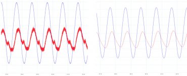
When measuring with my scope, I noticed that the crosstalk products carried quite some noise. My scope has the feature to filter the 1Khz signals, main and crosstalk, into neat sinewaves, see image below.
Doing that gave me the before mentioned angles of resp. 45 and 135 degrees for crosstalk L-R and R-L, which made me puzzling why these angles ?
Therefore performing the test again but now with the Adjust+ software, gave me two times almost 90 degrees, probably meaning that this piece of SW does not filter the signal and is measuring the phase angle in a rather messy signal.
Now to conclude: Adjust+ only measures the phase angles of the crosstalk products to the other channels main signals.
When varying the HTA, this phase angle will change.
At the point where this phase angle is identical for L and R, you have found the correct HTA.
By varying now the VTA, the phase angles for both Crosstalk signals should change in the same way and be tuned to 90 degrees.
Ninety degrees phase shift for both channels is a figure that makes sense, but 45 and 135 degrees seemed illogical.
Obviously a scope with filter feature is more accurate for adjusting the HTA and VTA than is possible with Adjust+.
On the other hand, the difference in final adjustment between the two methods is so small, that in practice it will not make any audible difference.
That leads me to the important question, why building a complex piece of SW to emulate the RCA patent when a simple series of measurements as performed by Adjust+ suffices ?
Hans
P.S. The crosstalk signal in the image below has been magnified 20x.
Attachments
Last edited:
Speaking of technical things, I was wondering what bitrate and bit depth we might want, and what the file sizes might me for later storage and downloads.
A 32 bit float file at 192K sample rate is 88 MB per stereo minute. Meaning a little over 2 Gig for a 25 minute LP.
But GZ likes FLAC files, which are lossless compression and 24 bit. That brings average files size down to around 14 MB. Meaning we could offer all the tracks at under 350MB. Not bad!
But do we need to use a 192k bitrate? If we want to try for a 50kHz sweep, yes, but wouldn't it need to be 1/2 speed anyway? If that's the case, do we need to go higher than 96k bitrate? Open for discussion.
Scott,
Could you describe in more detail what you did.
Apart from mentioning that you were using a Hilbert transform, I could not find any further info.
In the patent, at first the 400hz component was removed from the input signal. Next the remaining AM component was removed by squaring the filtered signal. Following step was to extract the 400Hz modulation signal from the 4Khz signal.
With a (steep) Hilbert bandpass filter the output phase will show the original 400Hz FM modulator signal, but you still won’t have the 400hz input filter followed by squaring the signal to remove all further AM modulation, meaning that the Hilbert phase output will be corrupted to some degree.
You see no difference when raising your LP, that’s the reasom I’m asking for details.
Hans
Scott,
Could you describe in more detail what you did.
The Hilbert transform is not a filter. It directly gives the instantaneous frequency and amplitude of a sine wave. Here 4kHz is a DC output and the 400Hz FM is on top of that (instantaneous frequency). It inherently rejects AM by a large factor.
We still have a misunderstanding. The RCA patent does not apply to simply squaring the cartridge/stylus/motor assembly with the groove. It finds the SRA that gives the best match between stylus and cutter head arc of travel. This must use two frequencies.
The STR120 has the sequence 1kHz 0dB left, right, lateral, vertical. The waveforms don't look at all like yours, the crosstalk is 180 degrees out of phase and changes only infinitesimally with raising and lowering 1 degree. It's possible this low cost cart and stylus geometry has no sensitivity to this test?
- Home
- Source & Line
- Analogue Source
- Test LP group buy