To be precise the instantaneous frequency is a simple computation from the phase of the Hilbert transform, the magnitude is the instantaneous amplitude.
more stuff VTA
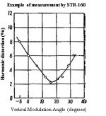
This is what I see a 1 degree change makes very little difference. BTW this STR160 LP was never offered by Old Colony and is probably virtual unobtainium. Each track had a different angle on the cutter. Ask them Pano. 😀
more stuff VTA
This is what I see a 1 degree change makes very little difference. BTW this STR160 LP was never offered by Old Colony and is probably virtual unobtainium. Each track had a different angle on the cutter. Ask them Pano. 😀
Attachments
Last edited:
The Hilbert transform can be implemented as a transversal bandpass filter thereby acting as FM demodulator, seeThe Hilbert transform is not a filter. It directly gives the instantaneous frequency and amplitude of a sine wave. Here 4kHz is a DC output and the 400Hz FM is on top of that (instantaneous frequency). It inherently rejects AM by a large factor.
We still have a misunderstanding. The RCA patent does not apply to simply squaring the cartridge/stylus/motor assembly with the groove. It finds the SRA that gives the best match between stylus and cutter head arc of travel. This must use two frequencies.
The STR120 has the sequence 1kHz 0dB left, right, lateral, vertical. The waveforms don't look at all like yours, the crosstalk is 180 degrees out of phase and changes only infinitesimally with raising and lowering 1 degree. It's possible this low cost cart and stylus geometry has no sensitivity to this test?
Demodulate FM-modulated data - Simulink - MathWorks Benelux
The phase output will give you the 400Hz modulator signal.
But before that, you will have to remove the 400Hz from the incoming signal followed by squaring the signal, see picture below. So I don't see where we have a misunderstanding regarding the patent.
At the point where the VTA equals the cutting angle, the demodulated signal should become zero.
And indeed, this is a complete different procedure as followed by Adjust+ with just one single 1Khz tone in one channel and measuring the crosstalk amplitude plus phase in the other channel.
Hans
Attachments

Hi Johnny,
You don't want to involve the speaker response in this at all. Your signal pick-off point could be a tape output from the preamp or receiver.
If you corrected from the speaker output, what would it sound like from the CD player or the tuner (or any other source material)? At the moment, all sources are referenced to the line level signal buss (record out for consumer equipment).
-Chris
The "correction" would take place at the MM phono pre or MC transformer / preamp; there would be no effect on other inputs. Many such devices have built-in adjustments for these parameters, and you can always use a "Y" cable and a phono connector with an appropriate resistor / capacitor if none is provided.
HF response of cartridges is significantly affected by capacitance and MC parallel resistance; this after the correct step up ratio was selected. I'm sure you knew that though. Perhaps you misunderstood what I was seeking or my language was clumsy.
I am not suggesting there be any equalization at line level or at the loudspeaker itself. In fact that's exactly what you don't want ... get a good line level response curve through the usual methods (choice of amplifier, loudspeaker, room EQ, etc) that is desirable with a digital or non-phono analog source, then adjust the phono pre to get a good cartridge response. Naturally it would be very helpful for those who change cartridges from time to time as well.
A 1KHz reference tone and a reasonably high frequency tone to accompany it corresponding to the beginning of a typical rising or falling point (14~16 KHz), or a bit higher since that may be more useful (17~18KHz), would be helpful in setting up cartridges.
Certainly there is more than one way to measure the resulting changes, and "by ear" is one of them, as is using a tape/processor out or preamp out itself, but with inexpensive, calibrated microphones (most come with a downloadable response curve based on Serial Number) available for a C-note, and free smartphone SPL meters (as long as the values are the same, the smartphone's mic response is still useful even if marginal at high frequency) using the speaker output, even comparing a digital file of the same frequency vs your cartridge response at those frequencies from the test LP, seems a simple enough, and useful, solution to me.
Last edited:
The phase output will give you the 400Hz modulator signal.
But before that, you will have to remove the 400Hz from the incoming signal followed by squaring the signal, see picture below. So I don't see where we
Yes I just filter out everything below 2K or so using an FFT filter, it has no useful information. The squaring is not necessary here the magnitude function does that, the square root of the squares of the real and imaginary parts.
With a little post filtering to manage noise this is all you need, where sig is the sampled signal and FS is the sampling frequency. All my transforms are on the entire signal. Save an occasional glitch at the beginning of a waveform this gave the same results as LD.
z = hilbert(sig)
instfreq = Fs/(2*pi)*diff(unwrap(angle(z)))
instmag = abs(z)
Last edited:
😱 Yeah, well maybe for the second addition.Each track had a different angle on the cutter. Ask them Pano. 😀
O.K. so the high pass filter at the signal input has been implemented.Yes I just filter out everything below 2K or so using an FFT filter, it has no useful information. The squaring is not necessary here the magnitude function does that, the square root of the squares of the real and imaginary parts.
And to generate the imaginary part of this filtered signal you must be using the Hilbert Transform, right ?
Then the square root of the sum of the squares, real and imaginary, gives you the envelope of the signal being the wanted 400Hz modulator signal.
Is that what you did ?
I still think that you will have to remove the amplitude information after the 2KHz input filter by using an axis crossing detector, since all AM information is carried forward in your Hilbert transform and in the Envelope detector.
I wrongly used the word squaring instead of axis crossing detection in earlier postings, meant to making a square wave, but this word is of course very misleading.
Hans
I still think that you will have to remove the amplitude information after the 2KHz input filter by using an axis crossing detector, since all AM information is carried forward in your Hilbert transform and in the Envelope detector.
The AM rejection of the transform is almost perfect, I posted a plot in the other thread.
Turntable speed stabilty
Right now I'm listening to one of my better Bob Ludwig mastered LP's with and without the pad, this is a don't care for me maybe someone else can make an argument for a VTA setting track.
I think those of us with more extreme stylus profiles (and Hans has one of the most extreme in the business) will find more change. Of course if the extreme profiles are worth effort is another discussion. But a repeatable method for optimising VTA would be good. Whether that is on this record or we have to buy the Feikert record and use the analytical techniques that have been developed here I have no strong opinion.
I figure one might as well take this rare opportunity to include as many test tracks missing from 'standard' test records, rather than just to replicate tests which already exist. It would be easy to do a 'me too' record, but not very satisfying or purposeful, methinks.
Unfortunately this all takes a little time, because one has to work out and discuss what those tracks are and synthesise them properly. Not only so they test what is actually worthwhile and useful to measure, but also so they are possible to cut and playback (which half of the tracks on the current proposal aren't, BTW...........)
LD
This is because the difference in geometric harmonic distortion in real programme material is barely audible, if at all. No surprises that one often can't detect it, methinks. However, I'll venture this is in a setup where stylus-groove friction is small enough not to cause secondary issues due to SRA and stylus attitude.Right now I'm listening to one of my better Bob Ludwig mastered LP's with and without the pad, this is a don't care for me maybe someone else can make an argument for a VTA setting track.
Consider another case where stylus attitude (eg SRA) critically affects stylus-groove friction, and mistracing/mistracking can occur because the stylus can ride up the inner groove wall. This, IMO, is the more common audible phenomenum wrongly attributed to geometric harmonic distortion. In this case, small changes in SRA can bring about big changes in both harmonic distortion and mistracking. Sometimes especially sibilance.
It can be particularly prone on fine radius styli, IME. Hence the 'precise sweet spot' often reported for VTA setting. Actually it is SRA that matters, due to presentation angle of the stylus-groove interface.
One might hope that manufacturers get the setting of SRA on the cantilever optimal, and that 'all' one has to do is get the VTA right by setting the cartridge dead parallel to the record. However, this is often reported not to be the case, and an offset to SRA/VTA of a few degrees is reportedly therapeutic. Common wisdom has '92.5 deg' or so, but I suspect there's no single optimal value, except on a case by case basis.
Unfortunately, the audible benefit from hitting the sweet spot can be profound: IMO the explanation lies in reduced stylus-groove friction whose benefits I've set out ad nauseum elsewhere.
Anyways, this is why a means of setting optimal VTA is extremely important: not for geometric reasons, but for stylus-groove interface SRA optimisation.
So rests the case for the defence 😉
LD
So rests the case for the defence 😉
LD
You're right as usual, I was just a little frustrated that I probably can't confirm the theory with my setup. I'm certainly still going to help get the tracks and post processing right. The LP BTW was a grammy winning David Burge piece with some intense contrasts and vocal sibilance.
Yes, as to geometrically induced distortion - my post above references a probable explanation of the enigma IMO.To be precise the instantaneous frequency is a simple computation from the phase of the Hilbert transform, the magnitude is the instantaneous amplitude.
more stuff VTA
This is what I see a 1 degree change makes very little difference. BTW this STR160 LP was never offered by Old Colony and is probably virtual unobtainium. Each track had a different angle on the cutter. Ask them Pano. 😀
To quote Yosh's site "Its [VTA error induced] distortion is usually inaudible at the lower recorded level than 5cm/s and angle difference less than 10 degrees"
The STR160 graph doesn't disclose the recorded level, but to obtain such gross harmonic distortion figures requires an extreme test level. At such levels, there's typically as much chance of mistracking as mistracing - see the original patent upon which the SW idea is based. Chances are the measurement is for mistracking performance, ref my comments as to SRA induced probable causes.
LD
The AM rejection of the transform is almost perfect, I posted a plot in the other thread.
Just to satisfy my technical curiosity, I will process your files from posting 313 and see what it brings.
About the importance of VTA and this added to your current experience, wasn't this exactly what was mentioned in the link in posting 346 ?
So from an acoustical point of view, we should take this issue with a grain of salt.
Hans
Just to satisfy my technical curiosity, I will process your files from posting 313 and see what it brings.
But there is both AM and FM at the same frequency here so the results are difficult to interpret. I also suspect the background tracing distortion here contaminates any useful information. What I did earlier was to use AM and FM synthetic signals at different frequencies (actually the AM was gross steps in amplitude change) to compare with LD's method. You really need to synthesize a signal to test the algorithm there are too many confounders in real data.
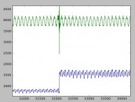
EDIT - I just repeated that test on that file. The plots are frequency (4k) and amplitude in LSB's with a 6dB step in gain. There is only a transient that is not filtered out.
EDIT EDIT - I just noticed something that I missed before. Looking at the left - right - vertical tracks (1K) at the same amplitude the left/right (by eye) have far less distortion than the vertical. In fact the distortion is easily seen by eye alone. It measures at least 10dB worse 2.2% to 6-7%.
Attachments
Last edited:
I did some research on setting VTA by equalizing the crosstalk and then looked at my data again. The left - right - vertical - lateral sequence from any number of test LP's yields the necessary data, this is well known and it's my problem for not being familiar with this. If you have a cartridge with very low crosstalk in one channel this technique can fail.
I also found this from the venerable TAS.
Follwed by a tedious process using a microscope and special software.
You got me here how do you adjust azimuth after the SRA without changing the SRA?
I also found this from the venerable TAS.
Step five is setting stylus rake angle (SRA)—a variant of what we used to call setting VTA (vertical tracking angle) back in the day.
Follwed by a tedious process using a microscope and special software.
Step six of Andre’s setup is adjusting azimuth. There has been a lot of nonsense written about azimuth—some of it, alas, in the pages of TAS. Trust me: Azimuth matters, and getting it right doesn’t just confer a theoretical advantage; you can readily hear the difference (as you can with SRA).
You got me here how do you adjust azimuth after the SRA without changing the SRA?
VTA
I could not find technical information about Neumann's SX-84 used also by GZ Vinyl, but found SX-74:
http://www.vintagewindings.com/gen pop/8299543VW8335/NeumannVMS/Neumann-SX-74.pdf
It mentions 15° by DIN45542 and 20+/-5° by IEC 98, and they settled at a compromise 18°.
I wonder if the SX-84 changed it eventually to 20°.
Also Ortofon recommends 20°, see 2.4 here:
FAQ & Installation
Some more info, here the change from 15° to 20° is said to have happened appr. 1975:
How to adjust the VTA of a turntable | PS Audio
You have piqued my curiosity as GZ can cut DMM. It would appear on a brief scan that DMM cuts at 0 degrees, electronically processed so it can be played back with standard playback cartridges. I need to read more on this when I get some time.
But does raise the opportunity of getting tracks with different cutting angle done easily if we need it, whilst putting in the negative that we need to check that the processing doesn't affect any of the more erm, unusual tracks we are thinking of.
But does raise the opportunity of getting tracks with different cutting angle done easily if we need it, whilst putting in the negative that we need to check that the processing doesn't affect any of the more erm, unusual tracks we are thinking of.
Some more info, here the change from 15° to 20° is said to have happened appr. 1975:
How to adjust the VTA of a turntable | PS Audio
That link is pretty weak in the maths, do they realize how much you have to raise the arm pivot to get 5 degrees?
- Home
- Source & Line
- Analogue Source
- Test LP group buy