GZ company have been continuously producing vinyl records since 1951. BTW, their location is about 30 km from my office.
In 1971, they issued 3 different Test measuring LP records. For those who might be interested, the link is
Měřici Gramofonova Deska - CDs and Vinyl at Discogs
but only in Czech language. I still own and use the record No. 3.
In 1971, they issued 3 different Test measuring LP records. For those who might be interested, the link is
Měřici Gramofonova Deska - CDs and Vinyl at Discogs
but only in Czech language. I still own and use the record No. 3.
Hi Pavel,
Can you post the track list for us?
I assume that since you still use it, there is value in looking at it. Any changes you would have done?
-Chris
Can you post the track list for us?
I assume that since you still use it, there is value in looking at it. Any changes you would have done?
-Chris
You are right, sorry. It's 20 mm resulting 5° (9" arm).We must be using different definitions? Assuming the tracking force is the same I don't see how the change is not ~atan(.25/9) = 1.6 degrees.
EDIT - I just checked one setup procedure and that is what they gave.
Hi Pavel,
Can you post the track list for us?
Hi Chris, here is the track list:
Test record No.3 Supraphon 1 19 1088
Side 1
315Hz mono at 5.42cm/s, continued by silent groove
315Hz 45°/45° 3.84cm/s left chan, continued by silent groove
315Hz 45°/45° 3.84cm/s right chan, continued by silent groove
1kHz 45°/45° left chan
6.3kHz 45°/45° left chan
1kHz 45°/45° right chan
6.3kHz 45°/45° right chan
Side 2
3150Hz 3.5cm/s
80Hz 20um amplitude
80Hz 30um
80Hz 40um
80Hz 50um
80Hz 60um
Hi Pavel,
Thank you. I'm looking at the tracks and I'm wondering which you find useful - and why? I would guess that the 45° modulated tracks are for azimuth?
I would be looking for 3150 Hz, 1 KHz and silence for the tests I'm thinking of.
-Chris
Thank you. I'm looking at the tracks and I'm wondering which you find useful - and why? I would guess that the 45° modulated tracks are for azimuth?
I would be looking for 3150 Hz, 1 KHz and silence for the tests I'm thinking of.
-Chris
Hi Chris,
the listed tracks serve for S/N, crosstalk, wow/flutter and trackability/distortion measurements and testing respectively.
the listed tracks serve for S/N, crosstalk, wow/flutter and trackability/distortion measurements and testing respectively.
The correct formula is...
The correct formula is:
e) None of the above.
atan(y/x) = atan(0.25/9) = 1.5911403 degrees
But, consider the heuristic example in which we raise the pivot the full effective length of 9 inches:
atan(9/9) = 45.0 degrees, which is wrong because if we raised the pivot a full 9 inches it would be hanging vertical, and the angle should be 90 degrees.
The correct formula is:
asin(y/r) = asin(0.25/9) = 1.5917542 degrees
As a verification check, if we raise the pivot the full effective length of 9 inches, then asin(9/9) = 90.0 degrees, which is as we would expect.
In this case, the error doesn't show up until the fourth decimal place and is of no consequence, but applying the wrong formula for other calculations involving tonearm geometry can result in significant errors. The atan(y/x) formula may have appeared elswhere on the internet but for this application it is technically incorrect.
No offense meant to anyone!
Ray K
We must be using different definitions? Assuming the tracking force is the same I don't see how the change is not ~atan(.25/9) = 1.6 degrees.
EDIT - I just checked one setup procedure and that is what they gave.
The correct formula is:
e) None of the above.
atan(y/x) = atan(0.25/9) = 1.5911403 degrees
But, consider the heuristic example in which we raise the pivot the full effective length of 9 inches:
atan(9/9) = 45.0 degrees, which is wrong because if we raised the pivot a full 9 inches it would be hanging vertical, and the angle should be 90 degrees.
The correct formula is:
asin(y/r) = asin(0.25/9) = 1.5917542 degrees
As a verification check, if we raise the pivot the full effective length of 9 inches, then asin(9/9) = 90.0 degrees, which is as we would expect.
In this case, the error doesn't show up until the fourth decimal place and is of no consequence, but applying the wrong formula for other calculations involving tonearm geometry can result in significant errors. The atan(y/x) formula may have appeared elswhere on the internet but for this application it is technically incorrect.
No offense meant to anyone!
Ray K
These are all small angle approximations, I don't see your point. There are no useful calculations where the tonearm or cartridge are displaced more than a small amount from ideal. Also if you adjust overhang at the same time it maintains the 9".
Last edited:
If someone is in the possession of both the STR112 and a Cart with an elliptical stylus, it would be nice to receive .WAV files the way that Scott did with a conical needle tip, preferably with three different VTA settings, like by inserting LP's below the STR112.
Only the vertical modulated signal with the 400Hz/4Khz is needed and only the first 30 seconds.
I will analyse these files, just to come to some advise whether it makes sense to include a 400Hz/4KHz lateral track on the envisaged test LP.
Hans
Only the vertical modulated signal with the 400Hz/4Khz is needed and only the first 30 seconds.
I will analyse these files, just to come to some advise whether it makes sense to include a 400Hz/4KHz lateral track on the envisaged test LP.
Hans
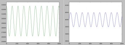
The strange "glitches" with a strong 25Hz content in the FM demodulated 4KHz signal, being there in the first revolution of the vertically modulated test track (see posting #379), are absent in the next 16 revolutions.
If this 25Hz was to be caused by the fres of the arm/cart combo, it would have appeared all over the place, but it doesn't.
And said 25Hz it is not AM but FM modulation of the 400Hz. This FM modulated 400Hz signal successively modulates the 4KHz signal. A nested double FM modulation so to say, that must have been generated by the cutting machine.
For measuring purposes, the first revolution should therefore be skipped.
Hans
Yes, it is still available - as it hasn't gone for mastering yet. 🙂. We will be sure to post and GB or other purchase details at the top of the thread.
The strong reason to include such a track is the premise that it offers a way of optimally aligning a stylus in 3D; where optimal means lowest stylus-groove friction and consequently best tracing. Rather than for reasons of geometric error induced harmonic distortion, which is normally tiny and negligible.If someone is in the possession of both the STR112 and a Cart with an elliptical stylus, it would be nice to receive .WAV files the way that Scott did with a conical needle tip, preferably with three different VTA settings, like by inserting LP's below the STR112.
Only the vertical modulated signal with the 400Hz/4Khz is needed and only the first 30 seconds.
I will analyse these files, just to come to some advise whether it makes sense to include a 400Hz/4KHz lateral track on the envisaged test LP.
Consider such a test track at 33.333rpm spindle radius 10cm, 400Hz/4kHz at +6dB ref 5cm/s. With an arbitrary lateral tracking angle error of 1 degree.
From Baerwald (1941), harmonic distortion ratio (virtually all 2nd) ε for a sine wave modulation, is given by
ε = vo tan(η)/rΩ
where
vo is modulation velocity
rΩ is linear rotational velocity
η is tracking angle error
For small tracking angle errors, as is the case here, that approximates to
ε = ηvo/rΩ
For the arbitrary +6dB test track conditions, as above, ε conveniently works out at 0.5%, almost entirely 2nd, harmonic distortion.
So far so good. Now we need to work out how much FM of our 4kHz tone to expect, by looking at the effect of 0.5% 2nd harmonic distortion at 400Hz on linear velocity error.
By superposition, the peak effect on linear velocity of 400Hz tone at +6dB is approximately εvo =0.005*0.1 m/s = 0.0005 m/s
As a fraction of rotational linear speed at this is 0.0005/0.35 = 0.14%
Therefore FM modulation of the 4kHz tone should be expected to be about 0.14%, if it arises from geometric causes, for a tracking angle error of 1%. This is pretty small, and though my SW can see it, I'm struggling to pick it cleanly out of the noise at a bandwidth of 400Hz so as to measure it.
The reason far higher levels of observed distortion/FM modulation sometimes reported, I figure, is probably due to another far bigger contribution, arising from mistracing due to stylus-groove friction. Or imperfect stylus geometry (ie not perfect shape). This, I believe, is what we are really seeing and testing here, and is very worthwhile.
This is why I consider the lateral 400Hz/4kHz test track very important, despite analysis of geometry showing theoretically otherwise. It's very probably an excellent indirect test of stylus-groove alignment in 3D
LD
Last edited:
If someone is in the possession of both the STR112 and a Cart with an elliptical stylus
Sorry, none here but I'll take it with a field recorder to Kevin's to see if we could sneak it in Saturday.
Why should we want to achieve the lowest friction ?The strong reason to include such a track is the premise that it offers a way of optimally aligning a stylus in 3D; where optimal means lowest stylus-groove friction and consequently best tracing. Rather than for reasons of geometric error induced harmonic distortion, which is normally tiny and negligible.
LD
You mention that distortion will be hardly affected, so what else could be the benefit apart from better tracing.
Is tracing supposed to be a problem ?
The Adjust+ test LP has a 315Hz/3150Hz stereo track 4:1 @ -10dB and a 3150Hz/1850Hz stereo track 1:1 @ -10dB.
I will play them both with different VTA's and measure whether HD and/or IMD are affected by these changes and come back with the outcome.
Hans

- Home
- Source & Line
- Analogue Source
- Test LP group buy