OK then.
For information but don't twiddle randomly.
The most critical adjustments are focus bias and E-F balance (if the player has adjustment for those as not all do).
Focus gain and tracking are relatively uncritical within limits.
Don't alter anything marked PLL or PLL lock.
And mark and also if possible take a picture of any settings first.
You can do but the pictures are for you 🙂
So you can come back to it and see where things were set. It's easy to forget.
First thing is to scope the RF though.
So you can come back to it and see where things were set. It's easy to forget.
First thing is to scope the RF though.
It depends on the player. Some have separate servo and signal processing chips. Other do it all in one.
Post a detailed photo of the internals of the player if you think it might help but it would have to be detailed and clear and even then no guarantees.
Post a detailed photo of the internals of the player if you think it might help but it would have to be detailed and clear and even then no guarantees.
The servo chip where is connected the focusing & tracking is Sanyo LA9200NM analog signal processor, pin 36 RF summing amplifier output, is there where have I to connect the probe scope? where have I to connect the gnd scope?
Yes, RFSM on the data sheet (summing amplifier output). The ground needs to be a clean ground related to that area of the circuit. If your not sure (and it's not always easy to determine which ground is which as they all essentially connect together anyway) then use the main chassis or audio ground.
You see the difference correct grounds make 🙂
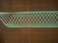
The first picture looks really good quality wise. Only comment would be the amplitude which is around 2.5 volts pk/pk going off your settings. That sounds extremely high.
(Worth just checking your scope to be 100% sure. If using a 1/1 probe then a DC check with a known voltage is OK. Make sure the trace deflects the correct amount. Check also using the cal output of scope to make sure no excessive overshoot (which would increase amplitude of HF signals displayed) If using a 10/1 probe make sure it is calibrated and compensated correctly)
What's the model number of the CD player ? Do you have a service manual that shows the RF level ?
All the players I have worked on have levels in the 1.2 to 1.5 v pk/pk range. So is this high level normal for that chip set ? I would make an exact note of the amplitude with a known disc (so you can come back to it). The only way to reduce the amplitude is to reduce the laser power which might be worth trying. You can always come back to where it was if needed.
The signal in the picture looks really clean. The only other adjustments I would attempt without knowing more are focus bias. That will be obvious on the scope display as it is adjusted. Adjust for clearest overall pattern and highest amplitude.
EF balance. This is a difficult one and requires experience to get a feel for what it does. If you scope the tracking error waveform and view at a lowish timebase speed and press track search or sometimes just "music search" within a track you see the error waveform jump about "above and below" a notional zero point (try AC coupling the scope). The pot is adjusted to give a symetrical "above and below" look to the waveform. When you see it it's obvious what is happening but mrak the pot carefully first.
And not mentioned... many CD problems can be mechanical such as sticking sled or faulty spindle motor. Make sure all these are attended too.
That amplitude needs confirming as whether correct or not though 🙂
You see the difference correct grounds make 🙂
The first picture looks really good quality wise. Only comment would be the amplitude which is around 2.5 volts pk/pk going off your settings. That sounds extremely high.
(Worth just checking your scope to be 100% sure. If using a 1/1 probe then a DC check with a known voltage is OK. Make sure the trace deflects the correct amount. Check also using the cal output of scope to make sure no excessive overshoot (which would increase amplitude of HF signals displayed) If using a 10/1 probe make sure it is calibrated and compensated correctly)
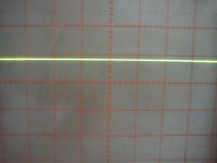
probe is 1/1, I used scope in DC setting but I only see a straight line, how can I do?
What's the model number of the CD player ? Do you have a service manual that shows the RF level ?
CEC TL1X, yes I have the service manual but don't shows the RF level
All the players I have worked on have levels in the 1.2 to 1.5 v pk/pk range. So is this high level normal for that chip set ? I would make an exact note of the amplitude with a known disc (so you can come back to it). The only way to reduce the amplitude is to reduce the laser power which might be worth trying. You can always come back to where it was if needed.
The signal in the picture looks really clean. The only other adjustments I would attempt without knowing more are focus bias. That will be obvious on the scope display as it is adjusted. Adjust for clearest overall pattern and highest amplitude.
EF balance. This is a difficult one and requires experience to get a feel for what it does. If you scope the tracking error waveform and view at a lowish timebase speed and press track search or sometimes just "music search" within a track you see the error waveform jump about "above and below" a notional zero point (try AC coupling the scope). The pot is adjusted to give a symetrical "above and below" look to the waveform. When you see it it's obvious what is happening but mrak the pot carefully first.
And not mentioned... many CD problems can be mechanical such as sticking sled or faulty spindle motor. Make sure all these are attended too.
That amplitude needs confirming as whether correct or not though 🙂
Remember a scope is really a real time voltmeter. So if you apply a known voltage (say 1 volt DC) the trace should deflect exactly one square at 1V/Div and so on. It's a good way to check basic accuracy.
I'm not familiar with the make and model I'm afraid.
I'm not familiar with the make and model I'm afraid.
It looks OK.
(Did you measure the battery on a DVM first 🙂 Might be more then 9.00 if its new.)
So all you need to do now is fix your player.. easy 😀
(Did you measure the battery on a DVM first 🙂 Might be more then 9.00 if its new.)
So all you need to do now is fix your player.. easy 😀
LM9200NM datasheet RF amplifier:
High level output voltage V36-H Rl 10kohms 4V min 4,2V typ 4,3V max
Low level output voltage V36-L Rl 10Kohms -1,6V min -1,3V typ -1.2V max
CEC manual service reference voltage for LA9200NM:
IC pin 36 0VDC
High level output voltage V36-H Rl 10kohms 4V min 4,2V typ 4,3V max
Low level output voltage V36-L Rl 10Kohms -1,6V min -1,3V typ -1.2V max
CEC manual service reference voltage for LA9200NM:
IC pin 36 0VDC
That's good then.
As to the player I really would try reducing the laser power slightly. Move the preset a fraction (if it were a watch face no more than two or three minutes) and recheck the amplitude to see you are turning correct way.
Make sure you turn the preset with the power off to avoid any possibility of damage.
Try reducing the amplitude down to around 1.5 volts pk/pk. If the player refuses to play then it seems as though the original setting is probably correct and so put the preset back by confirming the amplitude of the signal again.
As I say, all the players I have worked on have been around 1.2 to 1.5 volts pk/pk. There will always be one player and manufacturer that's different but until we know for sure it can do no harm to try it on a more "standard" level.
- Home
- Source & Line
- Digital Source
- Test CD for CD player adjustment