SY said:
1. Why is this an engineering desiridatum? Aren't the strands in electrical contact (unless horribly corroded)?
Thanks!
To avoid eddy currents, or at least minimize it.
Have you been on those free fall rides? Do you know how most of them stop? Well lots of these depend on reverse magnetic fields created by eddy currents induced by a moving magnet along a conductor. If a design can minimize eddy currents within the cable, then it also minimizes lots of complications.
I know for most people that have not studied in this field, it might not make sense. But it makes more sense among people to do this sort of thing often.
Well, I have some small familiarity with conduction effects but you bring up some things with which I'm not familiar. Can you start by telling me how to determine skin depth for the conductor geometry you're using?
SY said:Well, I have some small familiarity with conduction effects but you bring up some things with which I'm not familiar. Can you start by telling me how to determine skin depth for the conductor geometry you're using?
This is one site that I referenced early on.
http://home.san.rr.com/nessengr/techdata/skin/skindepth.html
In theory, skin depth varies with frequency. I'm sure it varies with geometry, but how, still needs to be investigated. That's why the speaker cables I purchased are flat solid conductors.
Yes, I saw that, but since that calculation is not a good model of your cable (or any other one with which I'm familiar), how do you determine skin depth? And, really, isn't it just the rise in impedance with frequency that you're after here, without regard to mechanism?
The model shows a single conductor in space and derives "skin depth" from that. Your cables have two conductors with equal currents but opposite direction in close proximity to one another in a dielectric medium. That's not what the model calculates. Why would you expect it to represent a totally different physical situation?
soongsc said:
I think jneutron is trying to anaylize what the human can detect and what the effects might be, and then look at speaker cable measurements and see if the differences make sense.
It's a big loop, but logical never the less.
You are indeed correct. However, what humans can detect will be a tad further along...at this instant, I am defining the spacial interaction of the two parameters we use for localization, ITD and IID..once everyone understands how these two entities work together to define a 2-d soundfield, then they will understand how those entities can be used to develop viable speaker wire measurements..and, what level of test capability is useless..
I can measure 8 ohm loads to under a percent accuracy at 400 volts per nanosecond, but that capability would transform back to a source positional accuracy of less than a thousanth of an inch, which is clearly ludicrous..but if you look at my graph 3, depth differential ITD sensitivity, you see that 10 uSec uncertainty in one channel reflects as a 20 inch uncertainty in source virtual depth position when the reconstructed image is 120 inches away and 20 inches off axis..
Re-interpreted, this means that if the cueing features within a source...like a female vocal, are time shifted by some lumped entity such as inductance, in a frequency dependent fashion, then the source of her entire spectra will not be a point in space, but rather, some curved line...
Think of the soundfield as a non orthogonal system of constant ITD lines overlapped by a grid of constant IID lines..if you specify an uncertainty of ITD and IID, you specify an uncertainty in position..
Cheers, John
No, it is not of any use to consider any discontinuity in the structure. It is however, important to consider the changes in the structure in terms of RLC, and in addition, skinning...which I see farther along in the posts...soongsc said:
If human sensitivity to IID and ITD were determined using signals of a transient nature, it seems logical to look at whether reflection of signals due to changes in conductor cross section throughout the current driven path might cause audible effects. Has anyone done testing in this respect? I suspect different cable design would effect this. I am tempted to do this using MLS type signals to see if there differences can be measured.
soongsc said:It's becomming rather difficult to find a speck of diamond in all this. I think the thread starter wanted a more constructive discussion.
Incorrect. To ascertain what to measure with a speaker cable, one needs criteria...until criteria are scientifically established, the question cannot be answered with any accuracy..
In point of fact, the answer is: the characteristic impedance of the speaker run must equal the load, and the effective dielectric constant of the speaker run must be 1, or as close to 1 as is physically possible..and the resistance must be as low as is practical.
At this time, I provide no supporting evidence to that assertion, as the math and understanding behind that needs to be understood, and I cannot provide that in one post..
Cheers, John
SY said:The model shows a single conductor in space and derives "skin depth" from that. Your cables have two conductors with equal currents but opposite direction in close proximity to one another in a dielectric medium. That's not what the model calculates. Why would you expect it to represent a totally different physical situation?
Why is it not appropriate to assume such until we can prove otherwise? Or maybe have some indication that this assumption might not stand true?
jneutron said:[snip]In point of fact, the answer is: the characteristic impedance of the speaker run must equal the load, and the effective dielectric constant of the speaker run must be 1, or as close to 1 as is physically possible..and the resistance must be as low as is practical.[snip]
John,
The characteristic impedance of a cable starts to play a role in the transmission of the signal if the signal wavelength starts to get in the vicinity of the cable length. Below that length, the signal transmission can be adequately described by modeling the cable as a lumped R, L, C. Only above that length should the model consist of a ladder-type network of distributed R, L and C. I'm sure I am not telling you anything new.
Where is the transition? The transition is not sudden but there is a range where it gradually changes, where the lumped model gets more and more inaccurate and the distributed model gets more and more accurate. Most engineers seem to put the transition at 1/4 wavelength. But lets play it save, lets take 1/10 wavelength.
For 20kHz, the electrical wavelength is some 19 KM (10 miles), which means that the characteristic impedance of cables would start to play a role at cable length of about 2 KM (1 mile) or more. I have the feeling that the majority of home-use speaker cables would probably be less.
Jan Didden
jneutron said:
You are indeed correct. However, what humans can detect will be a tad further along...at this instant, I am defining the spacial interaction of the two parameters we use for localization, ITD and IID..once everyone understands how these two entities work together to define a 2-d soundfield, then they will understand how those entities can be used to develop viable speaker wire measurements..and, what level of test capability is useless..
I can measure 8 ohm loads to under a percent accuracy at 400 volts per nanosecond, but that capability would transform back to a source positional accuracy of less than a thousanth of an inch, which is clearly ludicrous..but if you look at my graph 3, depth differential ITD sensitivity, you see that 10 uSec uncertainty in one channel reflects as a 20 inch uncertainty in source virtual depth position when the reconstructed image is 120 inches away and 20 inches off axis..
Re-interpreted, this means that if the cueing features within a source...like a female vocal, are time shifted by some lumped entity such as inductance, in a frequency dependent fashion, then the source of her entire spectra will not be a point in space, but rather, some curved line...
Think of the soundfield as a non orthogonal system of constant ITD lines overlapped by a grid of constant IID lines..if you specify an uncertainty of ITD and IID, you specify an uncertainty in position..
Cheers, John
Assuming all this is correct, what are the chances of this reflecting in improvement of the sound reproduction system? Would you be able to quantify in measureable terms what a speaker cable specification should be such that differences will not be audible among different brands?
I do not quote you because I have issues with your statements...rather, it is because of the interesting nature of your posts...and your nice dialogue...thank you for such...

That model, although taugh at undergraduate and graduate level, are WRONG!!!!!
To derive the current distribution in a round conductor, one needs to apply Faraday's law of induction to the INSIDE of the wire. At DC, inside a round cunductor, the magnetic field is circumfrential, zero at the center, and LINEARLY increases out to the surface of the wire..outside the wire, the field drops as 1/R.
When the current within the wire changes, you must apply Faraday's law to the differential elements within the wire...when that is done, you will see that the currents (eddy's)which are generated within the wire are toroidal in nature, and are opposing the main current within the wire at the center of the wire, and enhancing at the surface...THIS mechanism is responsible for the redistribution of current density within a SELF ENERGIZED conductor...that old skin theory model is USELESS for audio signals in normally sized conductors...
Since a cylindrical cross section of current density has within it...ZERO magnetic field, a cylinder also does not have the inherent 15 nH per foot inductive storage that is the storage penalty when using a uniform current density. I can provide references if needed, but I believe everybody's time is better spent staying away fro maxwell's equations.
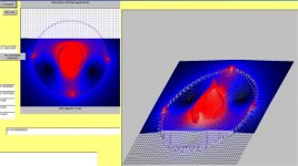
Because the current redistribution is a function of current SLEW rate, and since audio is chock full of wildly varying slew rates, the analytical solution of the energy being held within the wire, and the consequence of those lagging terms, is intractible at this time..I am developing a computer model to do such, but that is another thread...pic attached. this is the mag field intensity of a dipole iner cylinder surrounded by a quad outer cylinder....gotta have that gratuitous pic...😀
Cheers, John
The skin depth equations which are on the referenced web link, are incorrect.. If I see another link to another website that uses that terribly inaccurate exponential decay, planar TEM wave propagation model, I'm gonna just SCREAM.soongsc said:
As you know, RCL forms the impedance characteristic throughout the frequency range of interest. R alone is characterized at DC resistance. Since the cross section area size effects the DC resistance, the effective cross section area for a given frequency effects the resistance at that frequency. So if you use the skin depth of the highest frequency of interest to calculate the effective cross section area, and use that area as your cable thickness or radius for cable design, then the effective cross section is constant from that frequency down to DC, thus resulting in constant resistance through that frequency range.
That model, although taugh at undergraduate and graduate level, are WRONG!!!!!
To derive the current distribution in a round conductor, one needs to apply Faraday's law of induction to the INSIDE of the wire. At DC, inside a round cunductor, the magnetic field is circumfrential, zero at the center, and LINEARLY increases out to the surface of the wire..outside the wire, the field drops as 1/R.
When the current within the wire changes, you must apply Faraday's law to the differential elements within the wire...when that is done, you will see that the currents (eddy's)which are generated within the wire are toroidal in nature, and are opposing the main current within the wire at the center of the wire, and enhancing at the surface...THIS mechanism is responsible for the redistribution of current density within a SELF ENERGIZED conductor...that old skin theory model is USELESS for audio signals in normally sized conductors...
Since a cylindrical cross section of current density has within it...ZERO magnetic field, a cylinder also does not have the inherent 15 nH per foot inductive storage that is the storage penalty when using a uniform current density. I can provide references if needed, but I believe everybody's time is better spent staying away fro maxwell's equations.
Because the current redistribution is a function of current SLEW rate, and since audio is chock full of wildly varying slew rates, the analytical solution of the energy being held within the wire, and the consequence of those lagging terms, is intractible at this time..I am developing a computer model to do such, but that is another thread...pic attached. this is the mag field intensity of a dipole iner cylinder surrounded by a quad outer cylinder....gotta have that gratuitous pic...😀
Cheers, John
Attachments
jneutron said:
No, it is not of any use to consider any discontinuity in the structure. It is however, important to consider the changes in the structure in terms of RLC, and in addition, skinning...which I see farther along in the posts...
Incorrect. To ascertain what to measure with a speaker cable, one needs criteria...until criteria are scientifically established, the question cannot be answered with any accuracy..
In point of fact, the answer is: the characteristic impedance of the speaker run must equal the load, and the effective dielectric constant of the speaker run must be 1, or as close to 1 as is physically possible..and the resistance must be as low as is practical.
At this time, I provide no supporting evidence to that assertion, as the math and understanding behind that needs to be understood, and I cannot provide that in one post..
Cheers, John
I need to study your post a little more. But I must say you are one of the most constructive contributors that focusses on the results. 🙂
janneman said:John,
The characteristic impedance of a cable starts to play a role in the transmission of the signal if the signal wavelength starts to get in the vicinity of the cable length. Below that length, the signal transmission can be adequately described by modeling the cable as a lumped R, L, C. Only above that length should the model consist of a ladder-type network of distributed R, L and C. I'm sure I am not telling you anything new.
Jan Didden
Hi Jan
Did you get those calc units straightened out? I believe you didn't convert to inches, but to feet.
I must apologize for using those stupid inches and feet units, it is just one of convienience, and I have found that the simplest errors are unit conversions...I know from experience...

Your statements regarding transmission line theory are indeed correct..
However, I am not talking about the propagation of the signals along them. I am talking about the bulk energy storage within the line as a result of the L and C of the line..as it turns out, that storage of energy is a minima when the line Z matches the load Z..
I posted a graph showing that relationship earlier on..that would be post # 27.
Also, I have to chuckle when the topic of prop speed is bandied about by cable vendors...because it isn't the actual prop speed I worry about, it is the Effective Dielectric Constant...prop speed is directly related to the effective DC. Making the cable faster in prop speed...lowers the effective DC, lowering the bulk LC storage of the cable..
Cheers, John
soongsc said:
Why is it not appropriate to assume such until we can prove otherwise? Or maybe have some indication that this assumption might not stand true?
I think that jneutron has given some reasons why one might question the model you've cited. But stepping back, one must realize that when proposing a model which makes radical simplifications, it is necessary to justify them (at the least) or show some experimental evidence that one hasn't lost connection with reality by losing complication. In the link you cited, the author does neither.
I note that Bob Pease has suggested using flat ribbon cable as speaker wire. One could achieve the same geometry as some of those expensive wires, and have the flexibility to tune C and L.
janneman said:
John,
The characteristic impedance of a cable starts to play a role in the transmission of the signal if the signal wavelength starts to get in the vicinity of the cable length. Below that length, the signal transmission can be adequately described by modeling the cable as a lumped R, L, C. Only above that length should the model consist of a ladder-type network of distributed R, L and C. I'm sure I am not telling you anything new.
Where is the transition? The transition is not sudden but there is a range where it gradually changes, where the lumped model gets more and more inaccurate and the distributed model gets more and more accurate. Most engineers seem to put the transition at 1/4 wavelength. But lets play it save, lets take 1/10 wavelength.
For 20kHz, the electrical wavelength is some 19 KM (10 miles), which means that the characteristic impedance of cables would start to play a role at cable length of about 2 KM (1 mile) or more. I have the feeling that the majority of home-use speaker cables would probably be less.
Jan Didden
This is of common belief, and if there are none other factors that characterize the cable, then there would be certain R, L, C values beyond which differences are not audible. Does this make sense?
soongsc said:
Assuming all this is correct, what are the chances of this reflecting in improvement of the sound reproduction system? Would you be able to quantify in measureable terms what a speaker cable specification should be such that differences will not be audible among different brands?
In terms of absolute image presentation to a specified region of uncertainty, that will be rather easy. It will be rather simple to define the limits in time shift and variation in levels. By keeping the entire system under the limits, it will be possible to analytically derive how accurate image placement will be..
Now, the key word is this "absolute" image presentation..it is easy to say 1 nanosecond, and .000001 dB fluctuation allowed, and define the image to a millionth of an inch, but that is useless for audio...that is why I earlier stated, try a limit of say, one foot position uncertainty..once the spec limits are defined for that position accuracy, it can be tested with humans..
Humans have resolution limits for localization, and as fcserei has pointed out, actual hearing capabilities are just full of more limitations. That is why I am starting with point sources and ideal receivers, with no confounding influences like boundary reflections or comb filter effects..differential localization concepts are rather new (I've not found anything in the literature, this is my own development), and they are startlingly complicated. (I believe I state the obvious..)
As for the entire sound reproduction system, It is easy enough to define how a line cord can affect the sound, how a power wrap can, the selection of IC, diodes, capacitors, (I even hinted at how a tube amp is significantly different from the bulk of class AB solid state amps and was suprised to see that pass unfettered..)...I have defined those relationships, and can elaborate if desired on another thread..btw, it uses maxwell's equations, not some floobydust silly stuff I see on other sites..but evaluation of the impact of those things requires understanding what we are looking for...hence my differential localization..
Cheers, John
SY said:
I think that jneutron has given some reasons why one might question the model you've cited. But stepping back, one must realize that when proposing a model which makes radical simplifications, it is necessary to justify them (at the least) or show some experimental evidence that one hasn't lost connection with reality by losing complication. In the link you cited, the author does neither.
I note that Bob Pease has suggested using flat ribbon cable as speaker wire. One could achieve the same geometry as some of those expensive wires, and have the flexibility to tune C and L.
R L C terms are more of a macro level measurements, while skin effect is more the micro level, so I'm not sure whether looking at skin effect is simplifying the matter, but rather looking from different perspectives to see what makes sense.
I agree that tuning C and L provides means to optimize for a specific system or certain types of systems. But is there a certain cable characteristic combination that gets good such that one the spec is met, it different designs are indistinguishable?
jneutron said:[snip]Did you get those calc units straightened out? I believe you didn't convert to inches, but to feet.
[snip]Cheers, John
John,
Possibly I mad a mistake. Let me do it again: assume .8 c propagation speed in the cable (err on the low side), that's 2.4 x 10 ^ 5 km per second. At 20 kHz, one wave takes 50 uSec. So the wavelength in the cable is 2.4 x 10^5 x 50 x 10 ^ -6 which comes out to 12 km. At 1/10 wavelength, the cable characteristic impedance starts to play at 1.2 km cable length, not 2 km as I stated. Still, it wouldn't change my conclusion.
Jan Didden
SY said:I note that Bob Pease has suggested using flat ribbon cable as speaker wire. One could achieve the same geometry as some of those expensive wires, and have the flexibility to tune C and L.
Hi SY
Using the ribbon is an excellent way to play with L and C..there are, unfortunately, some limitations..
The magnetic environment of the end conductors of the ribbon are not identical to that of the bulk in the middle of the ribbon..as such, they will current share identically, and the outer wire on each side will tend to broadcast a bit more magnetic field, whereas the field along the face of the ribbon will fall off very fast, on the order of the conductor spacings.
As such, the best thing to do with the ribbon, is to form a cylinder, so that every wire sees the same magnetic environment.
The use of litz, or cat 5 braid styles do the same thing, but the design is attempting to keep all wires seeing the average same fields, and the graininess (or fineness) of the structure is being used to limit external magnetic field..
Flat ribbons do the same thing...good at the center, but mag field extends out at the edges...increasing inductive storage out there, and causing "skin effect" redistribution of high frequency currents across the cross section..
I really hate that term now...skin effect at audio frequencies connotes that stupidly inaccurate model, and doesn't help a bit in understanding reality..
Cheers, John
- Status
- Not open for further replies.
- Home
- General Interest
- Everything Else
- Technical discussion on loudspeaker cable