Neither. It is my own personally written code, using visual basic 6, running on windows 98, and a 500 mhz pentium...meaning, of course, that it is a slow slow pig.janneman said:What software is this? Something like Matlab or Simulink?
Jan Didden

I had to write sumptin to do force calculations for the wires I use at work..when we run 1.5 kiloamps through a 1mm diameter wire, it tries to repel it's mate, but we have to keep them together to minimize the dipole field they create, very important for low aspect ratio magnets....also, the wire forces in 5 to 10 tesla fields can add up...this software calculates the self exitation fields for the wires, and the wire forces, to allow us to figure out how strong the mechanicals have to be to limit wire movement in the 50 microinch range..otherwise, the wires will quench..
As I write it, I use existing results either from magnets we power, or other canned software, such as Roxio, as verification of accuracy..that, and balance of forces, which so far are accurate to about 1 part in 1015...this being a practical limit for the VB floating point package, as a single point calculation is a summation of hundreds of individual magnetic field producers.. The simu packages they use here are more powerful, and allow things like copper resistivity changes and iron saturation curves up to 10 tesla or so, all the way down to liquid helium temperatures..but since they approach the problem in a more analytical fashion, most of the "feel", or intuition is lost..you end up believing the results without understanding the method.
When I get a chance, I'll pop in the integral of the mag field for inductance calculations, then when I'm happy with the accuracy, start with the equations for current re-distribution.
Cheers, John
Although the pictures are nice, perhaps we should get back to wires??
I have referred to the "Effective Dielectric Constant" (EDC)...I will elaborate on that..
For a transmission line, the velocity of propagation is V = 1/sqr(LC) (eq 1)
L of course, dependent on the magnetic permeability mu, and C on the Dielectric Constant, epsilon.
Lower the inductance or capacitance, and you increase the prop speed...the limit being lightspeed.
For a coaxial line composed of both inner and outer cylinders, like braid, the equations are this:Ro is inner diameter of the outer conductor, Ri is the outer diameter of the inner conductor..
(hope you guys don't mind me not using html here, it is such a pain..
C = (2 PI epsilon)/ln(Ro/Ri) (eq 2)
L = (mu/2 PI) * ln(Ro/Ri) (eq 3)
Rearrange equation 2..
ln(Ro/Ri)= (2 PI epsilon)/C
Rearrange equation 3..
ln(Ro/Ri)=2 PI L/mu
set equivalency of the log ratio's..
2 PI epsilon/C = 2 PI L /mu
re-arrange... LC = 2 PI epsilon mu / 2 PI,
LC = epsilon mu (eq 4)
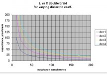
This is the complete derivation for the equation I posted earlier, that being L * C = 1034 * DC... (eq 5) note L is nH per foot, C in pF.
Now, equation 5 sets the bounding relation between inductance, capacitance, and DC..for a coaxial run. For any other wire pair or configuration, this equation sets the limit for what is possible given any dielectric. In point of fact, it is not possible to make a wire that has an LC product smaller than 1034 times the DC of the insulation, it is only possible to get higher.
I stated before, EDC. the definition...first, a limit: we will only discuss non magnetic materials, IOW, mu equals 1..
For any wire construct which is not coaxial, you will have a measured L and a measured C. The equation for EDC is :
EDC = L * C / 1034 (eq 6)
If the cable is 100% efficient at containing both the magnetic and electic fields (as a coaxial one is) , then the EDC will be equal to the actual DC. In the limit, very wide ribbon pairs can approach this, at least for DC applications..
If fields spill out, for example, a zip cord, then the EDC will be quite a bit higher than the dielectric...this is of course, the inductance increase of the fields around the wire..
From equation 1, V = 1/sqr(LC) , substitute equation 5 for L * C, this gives:
V = 1/sqr(1034 * EDC) (note that epsilon is actually epsilon absolute times epsilon relative..dc is epsilon relative.)
Again, the prop speed is proportional to the EDC of the system, and the EDC can be used for calculation of velocity.
Attached is a chart showing the relation of inductance and capacitance for four different dielectric coefficients..
Cheers, John
I have referred to the "Effective Dielectric Constant" (EDC)...I will elaborate on that..
For a transmission line, the velocity of propagation is V = 1/sqr(LC) (eq 1)
L of course, dependent on the magnetic permeability mu, and C on the Dielectric Constant, epsilon.
Lower the inductance or capacitance, and you increase the prop speed...the limit being lightspeed.
For a coaxial line composed of both inner and outer cylinders, like braid, the equations are this:Ro is inner diameter of the outer conductor, Ri is the outer diameter of the inner conductor..
(hope you guys don't mind me not using html here, it is such a pain..
C = (2 PI epsilon)/ln(Ro/Ri) (eq 2)
L = (mu/2 PI) * ln(Ro/Ri) (eq 3)
Rearrange equation 2..
ln(Ro/Ri)= (2 PI epsilon)/C
Rearrange equation 3..
ln(Ro/Ri)=2 PI L/mu
set equivalency of the log ratio's..
2 PI epsilon/C = 2 PI L /mu
re-arrange... LC = 2 PI epsilon mu / 2 PI,
LC = epsilon mu (eq 4)
This is the complete derivation for the equation I posted earlier, that being L * C = 1034 * DC... (eq 5) note L is nH per foot, C in pF.
Now, equation 5 sets the bounding relation between inductance, capacitance, and DC..for a coaxial run. For any other wire pair or configuration, this equation sets the limit for what is possible given any dielectric. In point of fact, it is not possible to make a wire that has an LC product smaller than 1034 times the DC of the insulation, it is only possible to get higher.
I stated before, EDC. the definition...first, a limit: we will only discuss non magnetic materials, IOW, mu equals 1..
For any wire construct which is not coaxial, you will have a measured L and a measured C. The equation for EDC is :
EDC = L * C / 1034 (eq 6)
If the cable is 100% efficient at containing both the magnetic and electic fields (as a coaxial one is) , then the EDC will be equal to the actual DC. In the limit, very wide ribbon pairs can approach this, at least for DC applications..
If fields spill out, for example, a zip cord, then the EDC will be quite a bit higher than the dielectric...this is of course, the inductance increase of the fields around the wire..
From equation 1, V = 1/sqr(LC) , substitute equation 5 for L * C, this gives:
V = 1/sqr(1034 * EDC) (note that epsilon is actually epsilon absolute times epsilon relative..dc is epsilon relative.)
Again, the prop speed is proportional to the EDC of the system, and the EDC can be used for calculation of velocity.
Attached is a chart showing the relation of inductance and capacitance for four different dielectric coefficients..
Cheers, John
Attachments
So from a cable structure point of view, which of the following types of speaker cable seem more promising?
1. Overlapped flat ribbon. (does twisting the the ribbon have effect at all on performance?)
2. Coaxial with solid round core and ribbon shield.
3. Coaxial with ribbon core (twisted or straight) with ribbon shield.
4. CAT 5 type cable.
5. braided ribbon rolled into a round shape.
6. normal twin leads.
Or there might be other structures? I guess we're trying to get our hands on best cables without spending $$$ trial & error.
It's very seldom that you can meet an engineer that actually talks with software code. There is only one other person that I have met that does that in a different field.
Low R and L...
according to the link (AES paper) I profided earlier a ribbon cable is best. Elsewhere (don't remember where ) I once read good thick coax is best. I have used transmitter cable (aircom +) for a while. Worked fine, but since I cannot hear the difference anyway, I now use plain mainswire because it's more flexible, and so easier to use.
according to the link (AES paper) I profided earlier a ribbon cable is best. Elsewhere (don't remember where
) I once read good thick coax is best. I have used transmitter cable (aircom +) for a while. Worked fine, but since I cannot hear the difference anyway, I now use plain mainswire because it's more flexible, and so easier to use.As I stated before, the lowest resistance and Z equal to the load. The question is, how to construct it..soongsc said:So from a cable structure point of view, which of the following types of speaker cable seem more promising?
1. Overlapped flat ribbon. (does twisting the the ribbon have effect at all on performance?)
2. Coaxial with solid round core and ribbon shield.
3. Coaxial with ribbon core (twisted or straight) with ribbon shield.
4. CAT 5 type cable.
5. braided ribbon rolled into a round shape.
6. normal twin leads.
Or there might be other structures? I guess we're trying to get our hands on best cables without spending $$$ trial & error.
The best approach is to think of it in terms of efficiency of geometry..the closer you get the EDC to the actual DC, the more efficient..
For the best efficiency, a double braid coaxial structure is the best. Use of an inner braid removes the 15 nH per foot penalty of a solid inner conductor, so it is not necessary to increase the capacitance to bring the Z back down to 8 ohms..
Plus side: I can make any Z I want, my first design (pic attached) was 10nH per foot, 288 pf per foot, EDC was 2.7, which is exactly the DC of the Tefzel insulation I used (hey, gotta check and re-check for consistency). The braid I used was just some stuff off a kilofoot roll of mike cable I have, so it is not low R.. It is easy to get nice braids which are #10 awg equiv, I am working with some of that now..
Neg side: To lower the EDC to about 1 requires thicker insulations, which requires larger cable diameter...for a Z = 8, a reasonable insulation with DC of 1.05 needs to be about 30 to 40 mils thick, this sets the inner diameter a tad larger than the heat shrink I have easy access to..overall structure will be about half to 5/8 inch diameter..
It also has bend restrictions..it's incredibly low inductance relies on the symmetry of a coaxial cylindrical structure, and bends tend to make the structure oval. The external cancellation of field may or may not remain cancelling if the shape goes oval, as that will be dominated by the modulus and thickness of the insulation and the overwrap pre-compression. IOW, total unknown..
Second choice for me would be cat 5 type stuff, multiple wires to lower inductance, braid to guarantee consistency in current sharing throughout the band.
Solid ribbons are ok, approach double braid in the dc limit, but current re-distribution at low Z load and high freq is unknown..
These choices, of course, are only of concern if the end application is sensitive to system shifts caused by the lumped RLC. For me, it is not a concern, and for most, the same..it is only if you intend to sit in the sweet spot, relatively motionless, and try to ascertain source positioning that I would even bother considering this cable stuff..me, I just enjoy the music no matter where I sit or what I'm doing..
My views of course, are based entirely on the reduction of the effect a cable will have on the delivery of power to a load....the scientific proof as to audibility require re-thinking what we can actually discern. Localization of source in binaural setups has not been properly applied to the problem, hence my derivations and work along those lines...I would prefer just the e/m end, but find I have to advance hearing research understanding in order to address this problem..
soongsc said:It's very seldom that you can meet an engineer that actually talks with software code. There is only one other person that I have met that does that in a different field.
My abilities in this respect are rudimentary in comparison to some of my co-workers...a very humbling workplace I live in..

You should see my 11 axis motion control machine and it's code...12 k lines of code so far, and some of the algorithms are still rudimentary..
Cheers, John
Attachments
Hey SY....boo
He He...happy nightmares...lower left...
Cheers, John
SY said:Re: Jackson
I still see that maroon cover in my nightmares.
He He...happy nightmares...lower left...
Cheers, John
Attachments

keyser said:Low R and L...
according to the link (AES paper) I profided earlier a ribbon cable is best. Elsewhere (don't remember where
That paper...not bad overall, just some errors..
Higher cable capacitance will tend to reduce the combined reactive component of the cable, thus lowering cable impedance at high frequencies and improving the high frequency response
What? This is not correct. Perhaps at frequencies where reflection coeff's are relevant, but certainly not audio.

Expressions for transmission lines (such as characteristic impedance...)....do not fit audio apps
Again, incorrect..as I pointed out, when line impedance matches load impedance, the storage of energy within the cable is minimized...using the "wavelength" argument is a mis-application of theory. If anyone cares to try, work through the equations for storage of energy within a wire...EL = 1/2 L I2, and EC = 1/2 C V2, and the equation for line impedance, Zline = sqr(L/C). If you do enough work, you will eventually get to the graph I put in post #27..
the skin effect was calculated and applied to the resistance where appropriate
Again, wrong...wrong skin equation, and, where is the drop of inductance as a consequence of current re-distribution?😕
These tests have shown that the best way to achieve adequately low resistance and inductance in a cable is by using many independent insulated wires per conductor rather than one large wire.
Nope, solidly nope...
My double braid construction blows that statement out of the water...nuked, big time...more hammers please?...
... thank you...perhaps he needs more "tests"...😉 Efforts to reduce the skin effect (such as litz construction) will help, but due more to the reduction of inductance that the reduction of the skin effect
tisk tisk...
Skin effect, by nature, is the reduction of inductance by the re-distribution of the current density towards a cylindrical structure..broad statements such as this, require massaging to be correct..masseuse?? ....thank you..Had I been a referee for this submission, in the present, these errors would have been removed prior to publication..at the time of publication, this was an excellent sota document...and I commend Fred for it..
Understanding moves on..
Oh, almost forgot the requisite pic...here's MY audio cables...#12/3, in neon colors, with neutrik connectors..color coded for length, 1+, 1-, and 2+ are used, the 2+ wired to allow the same cables be used for bridged application, rather than wiring separate cables for that. Tough to transport, but robust, in case one of the guys here runs it over with a forklift..
Cheers, John
Attachments

Re: Hey SY....boo
Well we have two books in common.
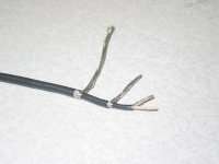
The black cables you first shown, seemed to have a total of four conductor layers rather than two. Use all of them? How do you measure these to determine they are 8 ohm?
jneutron said:
He He...happy nightmares...lower left...
Cheers, John
Well we have two books in common.
The black cables you first shown, seemed to have a total of four conductor layers rather than two. Use all of them? How do you measure these to determine they are 8 ohm?
Re: Re: Hey SY....boo
Good eye..
I needed a cylindrical entity to start with..so I used a coaxial cable as the inner core..because there is no electric or magnetic field within the core of a cylindrical current, the actual material in there has no consequences with respect to inductance, capacitance, skinning, or absorbtion..the choice of inner coax as a starter allows the feedback for the amp be picked from the speaker. This allows the amp to control the terminal voltage at the speaker, rather than at the amp, without picking up the B dot error associated with a simple voltage pickup scheme. (b dot is rate of change of magnetic field..at low impedances, the high slew rate of audio currents will generate loop voltages (faraday's law of induction), and those loop voltages will alter the time relationship of the signal being fed back..The accurate measurement of fast voltages and currents within a low impedance circuit is one of the most difficult things to do if e/m theory is not considered, so many do it incorrectly..and don't realize it.
It was never tested, I had sent the cables to a guy on the west coast to try..and he never returned them..oh, and, the outer two braids are used for the run..
For impedance measurement, TDR is of course the best way, unfortunately that requires a high bandwidth load, and a TDR which is capable of driving at 8 ohms..
The only practical way is to measure L and C, then calculate. But ya gotsta measure across the band of interest. To encompass the time domain we use for localization, roughly 2 to 5 uSec, the measurements should be performed up to about a Mhz...this is a requirement I kinda forced on Gene D over at AH...course, what to do with the info above 20Khz is currently unknown, but that will change..
What was I thinking...no pic😕 😕
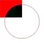
I stated that a cylindrical current distribution has no internal fields...here is the field map for a cylinder of wire..one quadrant copied for filesize limits...note that the green residue is the result of the graininess of the simulation structure. If I use more wires for the simulation, the green reduces..the magnetic anomolies tend to be about the same size as the conductor element spacings and go to zero in the limit of continuous conductors. But note, how black the interior is...no field...no inductance within..
Cheers, John
Well???what books in common😕 😕 🙂soongsc said:Well we have two books in common.
soongsc said:The black cables you first shown, seemed to have a total of four conductor layers rather than two. Use all of them? How do you measure these to determine they are 8 ohm?
Good eye..
I needed a cylindrical entity to start with..so I used a coaxial cable as the inner core..because there is no electric or magnetic field within the core of a cylindrical current, the actual material in there has no consequences with respect to inductance, capacitance, skinning, or absorbtion..the choice of inner coax as a starter allows the feedback for the amp be picked from the speaker. This allows the amp to control the terminal voltage at the speaker, rather than at the amp, without picking up the B dot error associated with a simple voltage pickup scheme. (b dot is rate of change of magnetic field..at low impedances, the high slew rate of audio currents will generate loop voltages (faraday's law of induction), and those loop voltages will alter the time relationship of the signal being fed back..The accurate measurement of fast voltages and currents within a low impedance circuit is one of the most difficult things to do if e/m theory is not considered, so many do it incorrectly..and don't realize it.
It was never tested, I had sent the cables to a guy on the west coast to try..and he never returned them..oh, and, the outer two braids are used for the run..
For impedance measurement, TDR is of course the best way, unfortunately that requires a high bandwidth load, and a TDR which is capable of driving at 8 ohms..
The only practical way is to measure L and C, then calculate. But ya gotsta measure across the band of interest. To encompass the time domain we use for localization, roughly 2 to 5 uSec, the measurements should be performed up to about a Mhz...this is a requirement I kinda forced on Gene D over at AH...course, what to do with the info above 20Khz is currently unknown, but that will change..
What was I thinking...no pic😕 😕
I stated that a cylindrical current distribution has no internal fields...here is the field map for a cylinder of wire..one quadrant copied for filesize limits...note that the green residue is the result of the graininess of the simulation structure. If I use more wires for the simulation, the green reduces..the magnetic anomolies tend to be about the same size as the conductor element spacings and go to zero in the limit of continuous conductors. But note, how black the interior is...no field...no inductance within..
Cheers, John
Attachments
So John, what's the trick with the "multi-braided" cable? Coax as signal, first brade return😕
You can see I'm looking for a quick & dirty, easy way out on yr expense😀
Cheers
You can see I'm looking for a quick & dirty, easy way out on yr expense😀
Cheers
John,
So the impedance should be also 8 ohms down to DC? With the speaker hooked up, wouldn't that cause a lose of half the voltage amplitude?
It might be compensated for if you use the terminal voltage feedback. Basically like making the amp source impedance 8 ohms.
Books in pic #126 post.
So the impedance should be also 8 ohms down to DC? With the speaker hooked up, wouldn't that cause a lose of half the voltage amplitude?
It might be compensated for if you use the terminal voltage feedback. Basically like making the amp source impedance 8 ohms.
Books in pic #126 post.
Gregm said:So John, what's the trick with the "multi-braided" cable? Coax as signal, first brade return😕
You can see I'm looking for a quick & dirty, easy way out on yr expense😀
Cheers
The double braid only needs two braids, the inner coax was just filler..
There is no trick..start with a tube, pull one braid over it..hold the braid tight, then heatshrink over that, pulling the heatshrink tight as is shrinks..this will make the structure of the braid visible through the shrink..then pull the second braid over that and final heatshrink or wrap over the second braid..it is important that it not be loose, and care needs to be taken not to damage the insulating layer between the braids.
Belden makes some triaxial wires, #88232 video triax, which has 2.6 ohms per kilofoot, #14 equivalent, inner and outer braid, with Fluorinated Ethylene Propylene as the inner jacket. They give the overall nominal diameter and the inner jacket dia, but they do not specify the inner shield diameter, so I cannot calc the Z of the double braid..the DC of the FEP is somewhere in the 1.8 to 2.4 range, I calculated this from the elec data on the Belden site, but I can't vouch for the accuracy of Belden's data..in the 32 wires I looked at, there were 3 gross errors..
Cheers, John
soongsc said:John,
So the impedance should be also 8 ohms down to DC? With the speaker hooked up, wouldn't that cause a lose of half the voltage amplitude?
No. sorry, bad explanation on my part..the characteristic impedance of the line should be 8 ohms...that is the impedance defined by Z = sqr(L/C).
It is not the series resistance. That should be low miliohms..
soongsc said:
Books in pic #126 post.
I meant, which of those books do you have?.
Cheers, John
jneutron said:
No. sorry, bad explanation on my part..the characteristic impedance of the line should be 8 ohms...that is the impedance defined by Z = sqr(L/C).
It is not the series resistance. That should be low miliohms..
Cheers, John
Ah! So throughout the thread we went though an intensive course based on all those "books" to finally arrive at the popular impedance matching thing.

I think its the Material one and the CookBook.
soongsc said:
Ah! So throughout the thread we went though an intensive course based on all those "books" to finally arrive at the popular impedance matching thing.
Pretty much so..however, the usual justification for matched impedance has always been some transmission line garbage pulled off some cable vendor's website..alongside with prop velocity garbage. As Jan pointed out in a roundabout way, sheer and utter baloney..
I actually stumbled across the relationship between the line impedance and the load impedance, with the match providing the least amount of energy storage..while I was massaging the design equations in my excel spreadsheet. That is also where I realized that prop velocity does indeed correlate directly to the effective dielectric coefficients, which again, correlates to the storage of the cable..maximize prop speed, minimize storage.
So, while the explanations were inaccurate, electrically, there may be sound reasons.. But their explanations are just ice cream science..
I still don't have a smoking gun relating this to what we hear, so absolutes are nonexistent..simply applying matched Z and low R as the criteria, while answering the overall thread question, does not mean that proof of that choice is correct...it minimizes effect, but is that audible, or even desireable...the big question.
Cheers, John
So now it seems we have narrowed down to the following considerations:
1. Minimum resistance, since this is pure loss and dissipation of energy.
2. Matched impedance, since we want to minimize energy storage. It's easier to make C bigger, keeping L to minimum first is probably the critical issue to produce the low impedance cable. That way C can be added when the length gets longer and adding C would not contribute to the series resistance.
3. Minimize eddy currents. Either due to opposite current induced magnetic fields or material induced.
If these can be optimized such that certain criteria are met, then theoretically speaker cables would be the same.
😀
soongsc said:2. Matched impedance, since we want to minimize energy storage. It's easier to make C bigger, keeping L to minimum first is probably the critical issue to produce the low impedance cable. That way C can be added when the length gets longer and adding C would not contribute to the series resistance.
3. Minimize eddy currents. Either due to opposite current induced magnetic fields or material induced.
If these can be optimized such that certain criteria are met, then theoretically speaker cables would be the same.
😀
On 2.. L and C are related to the geometry and the DC of the insulation. Making the cable longer increases both at the same time. I do not recommend adding capacitance as a lumped element as it does nothing to lower the storage energy..
On 3..eddy currents per se can only dissipate energy within the metals, and as a side "benefit", cause the current to re-distribute.
My thinking along skinning and eddy currents is this: lower frequencies have the most inductance in series due to lack of current re-distribution, highs will see less inductance..so higher frequencies will not be delayed as much..
This could easily be construed as "smearing", as some would call it..having the virtual image dispersed along a line based on frequency, instead of a point..
Caution!!!these statements, while technically accurate, DO NOT MEAN THAT THEY ARE RELEVANT TO WHAT WE HEAR!!!!
There is no factual evidence to prove these statements are in any way accurate for the audio band...just as there is no factual evidence showing they are not..
New understanding of human hearing is required..
Cheers, John
jneutron said:
On 2.. L and C are related to the geometry and the DC of the insulation. Making the cable longer increases both at the same time. I do not recommend adding capacitance as a lumped element as it does nothing to lower the storage energy..
On 3..eddy currents per se can only dissipate energy within the metals, and as a side "benefit", cause the current to re-distribute.
My thinking along skinning and eddy currents is this: lower frequencies have the most inductance in series due to lack of current re-distribution, highs will see less inductance..so higher frequencies will not be delayed as much..
This could easily be construed as "smearing", as some would call it..having the virtual image dispersed along a line based on frequency, instead of a point..
Caution!!!these statements, while technically accurate, DO NOT MEAN THAT THEY ARE RELEVANT TO WHAT WE HEAR!!!!
There is no factual evidence to prove these statements are in any way accurate for the audio band...just as there is no factual evidence showing they are not..
New understanding of human hearing is required..
Cheers, John
You're right that lumping capacitance has no benefit.
However, now that the speaker impedance varies all over the place, we would really want to make the speaker match what the cable is designed to do to get maximum benefit.
soongsc said:However, now that the speaker impedance varies all over the place, we would really want to make the speaker match what the cable is designed to do to get maximum benefit.
Agreed, very much so..I do not have the answer to that one.
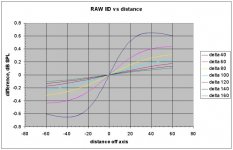
I have finished the first iteration of the IID spreadsheet calculations..I am somewhat taken aback at the numbers I am seeing...so much so, that I have to re-check the numbers.
But, I attach the first graph..it it the SPL difference between ears, for a source that is between 40 and 160 inches in front, and from -60 to 60 inches to either side.
If you look at the "delta 100" line, which represents the ear to ear spl diff for a source 100 inches away, this can be seen.
The difference in spl from center stage to 20 inches to the right, is .1 dB..that is very small. If we wish to keep an image stable to within a foot of where it is supposed to be, the system will have to be good to about .06 dB from one channel to another..from the initial ITD graphs, it appears to be about 50 uSec as well..
It is possible that IID is the more important of the two parameters.😕
Cheers, John
Attachments
There are lots of things that relate with localization:
IID and ITD as you have mentioned, but also the difference between a transient and reflections. Man is a continously learning machine that coorelates what is heard and what is seen, learned, then used to localize based on what one has learned. These studies would best be used to determine placing of multiple mics in the recording process.
If someone could come up with a software that could scan in a room interior, allow the user to point to where the performers will be, and then allow computerized calculation of optimum mic locationing, then this might be a big revolution in the recording industry.
This subject would belong in a different thread though.😀
- Status
- Not open for further replies.
- Home
- General Interest
- Everything Else
- Technical discussion on loudspeaker cable