jneutron said:I do not quote you because I have issues with your statements...rather, it is because of the interesting nature of your posts...and your nice dialogue...thank you for such...
The skin depth equations which are on the referenced web link, are incorrect.. If I see another link to another website that uses that terribly inaccurate exponential decay, planar TEM wave propagation model, I'm gonna just SCREAM.
That model, although taugh at undergraduate and graduate level, are WRONG!!!!!
To derive the current distribution in a round conductor, one needs to apply Faraday's law of induction to the INSIDE of the wire. At DC, inside a round cunductor, the magnetic field is circumfrential, zero at the center, and LINEARLY increases out to the surface of the wire..outside the wire, the field drops as 1/R.
When the current within the wire changes, you must apply Faraday's law to the differential elements within the wire...when that is done, you will see that the currents (eddy's)which are generated within the wire are toroidal in nature, and are opposing the main current within the wire at the center of the wire, and enhancing at the surface...THIS mechanism is responsible for the redistribution of current density within a SELF ENERGIZED conductor...that old skin theory model is USELESS for audio signals in normally sized conductors...
Since a cylindrical cross section of current density has within it...ZERO magnetic field, a cylinder also does not have the inherent 15 nH per foot inductive storage that is the storage penalty when using a uniform current density. I can provide references if needed, but I believe everybody's time is better spent staying away fro maxwell's equations.
Because the current redistribution is a function of current SLEW rate, and since audio is chock full of wildly varying slew rates, the analytical solution of the energy being held within the wire, and the consequence of those lagging terms, is intractible at this time..I am developing a computer model to do such, but that is another thread...pic attached. this is the mag field intensity of a dipole iner cylinder surrounded by a quad outer cylinder....gotta have that gratuitous pic...😀
Cheers, John
I think the time difference and cable lag is mixing the sequence of our posts as we type.
For round conductors, what you mentioned seems true, how about flat solid conductors that use the same skin depth theory?
I referenced two sitesm are you indicating that both are not correct in theory?
Jan, I'm sorry...I wasn't talking about that calc...I was referring to your 1 inch 840 uSec number from yesterday.. you incorrectly converted 300 meters per second to acoustic velocity per inch..janneman said:
John,
Possibly I mad a mistake. Let me do it again: assume .8 c propagation speed in the cable (err on the low side), that's 2.4 x 10 ^ 5 km per second. At 20 kHz, one wave takes 50 uSec. So the wavelength in the cable is 2.4 x 10^5 x 50 x 10 ^ -6 which comes out to 12 km. At 1/10 wavelength, the cable characteristic impedance starts to play at 1.2 km cable length, not 2 km as I stated. Still, it wouldn't change my conclusion.
Jan Didden
As for this post, you need to re-read my post...I am not talking about delays along the cable...I am talking about the lumped LC storage of energy, and it's relation to characteristic impedance and load impedance..
Cheers, John
PS...yes, the thread is proceeding much too fast for everyone to understand the concepts...it is amazing how quick..
Konnichiwa,
May I ask why it is neccesary (again) to talk about "these expensive cables"?
Their price has no relation to anything else, but to the market. An economist would find the subject of interrest no doubt, to an engineer it is of zip consequence....
Are you interested in emulating expensive cables so you can pretend to own these expensive cables and to be able to tell others "look, my speaker cables are worth $ 10,000"? If not what has the price to do here.
As for flat cables, there are many ways to lower a cables inductance and as others have remarked this reduces the aparent CI of the cable assembly and results in minmal energy storage and if we correctly terminate such a cable with suitable RC zobels where R = CI and if we include a suitable pair of in-line inductors on the Amplifier side and another Zobel for amplifier stability we have made a cable that behaves very predictably.
I have proposed such designs to DIY'ers back in the lat 90's, over at TNT-Audio in my articles.
BTW, as all my current amplifiers are unconditionally stable I nowadays omit the inductors required to ensure no Amplifier (including NVA and Naim) oscillates. I use "interleaved" connection computer ribbon cable (silverplated copper in PTFE) with a CI around 3.3Ohm and of course suitable RC terminators on both Amplifier and Speaker end. This makes for a good looking, flat and affordable cable which offers very high subjective performance.
Sayonara
SY said:I note that Bob Pease has suggested using flat ribbon cable as speaker wire. One could achieve the same geometry as some of those expensive wires, and have the flexibility to tune C and L.
May I ask why it is neccesary (again) to talk about "these expensive cables"?
Their price has no relation to anything else, but to the market. An economist would find the subject of interrest no doubt, to an engineer it is of zip consequence....
Are you interested in emulating expensive cables so you can pretend to own these expensive cables and to be able to tell others "look, my speaker cables are worth $ 10,000"? If not what has the price to do here.
As for flat cables, there are many ways to lower a cables inductance and as others have remarked this reduces the aparent CI of the cable assembly and results in minmal energy storage and if we correctly terminate such a cable with suitable RC zobels where R = CI and if we include a suitable pair of in-line inductors on the Amplifier side and another Zobel for amplifier stability we have made a cable that behaves very predictably.
I have proposed such designs to DIY'ers back in the lat 90's, over at TNT-Audio in my articles.
BTW, as all my current amplifiers are unconditionally stable I nowadays omit the inductors required to ensure no Amplifier (including NVA and Naim) oscillates. I use "interleaved" connection computer ribbon cable (silverplated copper in PTFE) with a CI around 3.3Ohm and of course suitable RC terminators on both Amplifier and Speaker end. This makes for a good looking, flat and affordable cable which offers very high subjective performance.
Sayonara
R L C terms are more of a macro level measurements, while skin effect is more the micro level
What does that mean? And I still don't quite know what you mean by "skin effect." If you want an engineering discussion, you have to be precise about the definitions of technical terms, otherwise we're all talking past one another.
John, how does the charge distribution you show for the solid cylinder model conductor change with the close proximity of another conductor carrying an equal-and-opposite current? (Sorry, Jackson is 25 years in my past)
Their price has no relation to anything else, but to the market.
Man, it must be nice to be so rich that you just don't worry about costs. It must be even nicer to do an engineering job that doesn't involve cost control and reduction. I hope to experience both of these before I die.
Konnichiwa,
What I was referring to is the fact that in this day many items slightly above commodity levels are priced such that the actual content in terms of material cost, engineering cost and R&D bears little relation to the retail price. Usually the largest cost posts for such items tends to be marketing and distribution plus retailers profits.
This holds as true for Music CD's and DVD's as it does for specialist audio cables, car accessories, computer software etc....
In other words, if I took a given product and accepted a slightly higher retail price I could give dealers a larger margin and spend more on marketing and thus reliably increase my overall sales. I could even reduce overall product quality within certain bounds while cutting my own costs and with increased marketing and dealer margins would increase my sales AND at the same increase my profit margin.
By cutting retailers margins and saving on marketing and passing these savings through to the end customer either directly or by improving quality I would be out of business quick....
Sayonara
SY said:Man, it must be nice to be so rich that you just don't worry about costs. It must be even nicer to do an engineering job that doesn't involve cost control and reduction. I hope to experience both of these before I die.
What I was referring to is the fact that in this day many items slightly above commodity levels are priced such that the actual content in terms of material cost, engineering cost and R&D bears little relation to the retail price. Usually the largest cost posts for such items tends to be marketing and distribution plus retailers profits.
This holds as true for Music CD's and DVD's as it does for specialist audio cables, car accessories, computer software etc....
In other words, if I took a given product and accepted a slightly higher retail price I could give dealers a larger margin and spend more on marketing and thus reliably increase my overall sales. I could even reduce overall product quality within certain bounds while cutting my own costs and with increased marketing and dealer margins would increase my sales AND at the same increase my profit margin.
By cutting retailers margins and saving on marketing and passing these savings through to the end customer either directly or by improving quality I would be out of business quick....
Sayonara
Yes, the speed of this thread is something to contend with..soongsc said:
I think the time difference and cable lag is mixing the sequence of our posts as we type.
soongsc said:For round conductors, what you mentioned seems true, how about flat solid conductors that use the same skin depth theory?.
For a flat solid conductor, there will be current redistribution..as the frequency increases, the current will tend to move towards the edges of the ribbon. The proximity of a second, returning ribbon, will counter this..however, there will still be dipole fields extending along the edges outward along the plane of the ribbon...as the frequency goes up the inductive storage outside the edges of the ribbon will increase, because the current will redistribute towards the edges, so a larger fraction of the current will be in a position where the currents next to it cannot neutralize the internal fields. A double braid coaxial construction gets around this effect, remaining very stable in inductance and transmission line impedance across a large frequency band.
Note that for a flat conductor wound as an inductor, the current re-distribution towards the edges will be enhanced...those ribbon inductors have some other interesting features that are not a simple inductance...the same goes with electrolytics...while the classic model of the internal inductive reactance is good at low frequencies, it falls apart for some jelly roll constructs, depending on where the connections are made. If the connectons are made at opposite sides of the foil set, the current redistribution at higher frequencies will tend to starve the dielectric in the center..this is a large part of the reason electrolytics have roughly half the capacitance at 20Khz...look at the data sheets for that..but again, that is worthy of it's own thread, so I will not elaborate further..
soongsc said:I referenced two sitesm are you indicating that both are not correct in theory?
Overall, I see LeSeuf's article as being very good. He at least states the existence of the internal currents and inductive storage..
If you examine the link, you see the following good things...
First, he stated:
This is absolutely correct...use of the exponential approximation completely neglects the fact that the fields are due to the internal currents...key, key, key point...this is the point that Hawksford neglected...in that '85 "thing".In engineering textbooks, the consequences of finite conductivity and wire size are treated in terms of an ‘Internal Impedance’. This term is probably more useful that ‘skin effect’ as it acts as a reminder that the effects arise due to the fields internal to the conductor.
Equation 2 describes the effective inductance per unit length...Lo=mu/8 PI...this is the correct, this is the 15 nH per foot I speak of..
Note that he states outright, that for wire radius less than about 5 times the "skin depth", the numerical expressions for evaluating the bessels fall apart..
Note also, he says"the standard hf approximation"..and then, "however by inspecting", and then provides an approximation equation..confirming the inaccuracy of the hf skin model.
His article, however, does not illustrate what the eddy's look like, for either round, cylindrical, or flat conductors...not what he was trying to confer, I guess..
Cheers, John
SY said:John, how does the charge distribution you show for the solid cylinder model conductor change with the close proximity of another conductor carrying an equal-and-opposite current? (Sorry, Jackson is 25 years in my past)
Unfortunately, Jackson is alive and well, residing about 5 feet from me as I type...
Man, what a honker of a text...
As the wires get closer together, each will produce a field which will affect the other wire's total field..at DC, this results in a break in symmetry, and current slew will make the internal eddy's essentially track that mag field change...less field intensity, less eddy's. To the first approximation, this will cause the currents to re-distribute as a result of changing current...to the outside of each conductor..away from the other.
This poses a second problem..because the center of the currents is shifting away, the inductance of the magnetic field will now start to increase..recall Terman's equation for inductance:
L = .01016 * length * [{2.303 * log(D/r)}-{D/length}+{mu*delta}]
D is distance, r is radius, mu is 1, delta is a skin factor..
So, while current is redistributing, meaning delta will go down...the effective D is going up...
Again, a rather intractible equation..my gut says the inductance never really goes up at some frequency, but it will go down slower than real redistribution equations would predict..
That is why I'm writing that darn simulation code...in the end, I'll be able to make any conductor geometry I desire, and simply integrate the mag field at any freq to calculate the inductance and energy storage..that is a long but fun prospect for me..my friends here say "just use Roxio", but where's the fun in that?...anybody can do that..
Cheers, John
SY said:
It must be even nicer to do an engineering job that doesn't involve cost control and reduction.
Those were the good old days!
Don't know about your guys, but I'm getting bloodshot eyes just looking through all this stuff. Probably the best thread I've been through at this site.
jneutron said:
Jan, I'm sorry...I wasn't talking about that calc...I was referring to your 1 inch 840 uSec number from yesterday.. you incorrectly converted 300 meters per second to acoustic velocity per inch..[snip]
No, I didn't. And you didn't check, apparently. I merely converted 25.4 mm to 1 inch for your and the other non-metric guys' convenience. 1 inch = 0.0254 m, so 0.0254 / 300 gives 846 uSec. At least this I got correct.
Jan Didden
soongsc: Yes, quite cool! I knew that things would heat up when jneutron got here.
John: I sort of suspected that you'd need to do your numerical solution, but I was hoping that there would be a trick use of symmetry that would make things simple. Instead, we're left with a couple of factors that have to balance and that kills the idea of coming up with a meaningful approximation.
Re: Jackson
I still see that maroon cover in my nightmares.
Kuei Yang Wang said:[snip] ... to an engineer it is of zip consequence....
[snip]
Nice pun!😉
Jan Didden
Hmmm, your numbers...janneman said:
No, I didn't. And you didn't check, apparently. I merely converted 25.4 mm to 1 inch for your and the other non-metric guys' convenience. 1 inch = 0.0254 m, so 0.0254 / 300 gives 846 uSec. At least this I got correct.
Jan Didden
1 inch = 846 uSec...
10 inches = 8460 uSec = 8.46 mSec
100 inches = 84.6 mSec
1000 inches = 846 mSec
1182 inches = 1 sec
1 meter =39.4 inches.....1182 inches /39.4 equals 30 meters..you are off by a factor of 10...
Now, on this side of the pond😀 😀 😀 , my calculator say:
.0254 divided by 300 equals 8.466666 e-5
8.46 e-5 = 84.6 e-6..84.6 uSec..
As I said, the simplest errors are the most common..
btw, I did check...as I would expect of anybody here should I also make a mistake..
Cheers, John
SY said:John: I sort of suspected that you'd need to do your numerical solution, but I was hoping that there would be a trick use of symmetry that would make things simple. Instead, we're left with a couple of factors that have to balance and that kills the idea of coming up with a meaningful approximation.
Well yah...for now..
Here's a simulation picture of the magnitude of magnetic field around a rectangular conductor..it is composed of 100 wires, in a 25 by 4 array. Since this is NOT a depiction of a high frequency current re-distribution, but a DC one, it is sufficient as a model for deriving the DC magnetic fields to a point..I use magnitude for this, as coloration based on field line direction and intensity is just a tad more difficult to understand..I can make those pics, but trust me...while pretty, is very confusing...😕 😕 😕
For this software, I have black as zero field, blue as middle, red as highest field, in gradations..the view is close to the wire, so there is no outside black regions...
The spikes and dips in the pic are a result of using individual current conductors...the math goes wild if the calculation point gets too close to a current, the currents are singularities..
The most significant thing to see is the center of the conductor..note that there is a dip in the field there, as indicated by the blue. Also note, that the dip in the field along both long edges is evident..
When this conductor is driven by high slew rate currents, the higher field locations will create the higher eddy's, this is where the currents will be drawn..
Please excuse the fuzziness, this 100K file size is too small..
Cheers, John
Attachments

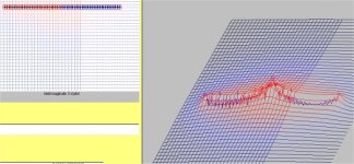
Here's a pic of a pair of ribbons..
Note that the magnetic field is highest in the center..this is the classic dipole field, just elongated..and it will react differently to high current slew rates.
Also of note, the field around the ribbons...it's almost zero, the black field is everywhere...
I made the software auto-range field intensity so that the peak field is the same in all cases, colorwise and vertical wise, so you can't simply compare both pics to get a feel for absolute field strengths...but it is quite powerful for showing how the fields tend to congregate..
Cheers, John
Attachments

John, many thanks, very illuminating. How about side by side? (I love taking advantage of free labor!)
SY said:John, many thanks, very illuminating. How about side by side? (I love taking advantage of free labor!)
Ummm, SY? (look up) You mean, like that?
Cheers, John
SY said:The posting is running fast and furious- I missed it!
Ya snooze....ya lose..
I wasn't sure which side by side you wanted, so I started this one...it is side by side, not overlapping..notice the thing spashed field all over the place, it's definitely higher inductance positioning..no control, what a mess!!
 somebody call a cleanup crew..
Case anyone asks...the software runs at different scan resolutions..really coarse ones, then finer and finer..what I've been taking snapshots of is the next to last scan, which is a roughly 50 line by 50 line vector presentation..the last scan is about 3 times the resolution, which provide solid coloration of the fields..The vector lines provide a clearer depiction of the fields for simple discussion, as the slope of the field intensity can be seen.
John
Attachments
- Status
- Not open for further replies.
- Home
- General Interest
- Everything Else
- Technical discussion on loudspeaker cable