soongsc said:Hey, if you can point us to what has already been said, it would sure give us a heads up on what's going on.
My apologies..I have been trying to make the graphs understandable..
I can point all to what has already been said, unfortunately, that is horribly inadequate.
Current published research does not consider the differential ITD and IID required for the localization of sounds. Without consideration of those parameters, it is not possible to determine the effect on the virtual soundstage of the parameters R, L, C, and Q of the speaker wires. (it is not possible to determine level of effect, if you don't know how we hear).
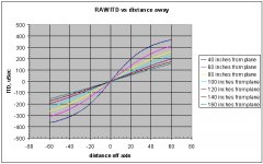
I've been crunching the numbers for ITD only so far, here is a graph. This graph represents the difference in arrival time between the ears, for a source which is a distance of 40 to 160 inches from the plane of the listener, and at a distance x axis inches off the centerline of the listener's line of sight.
When the source of sound is 40 inches from the plane of the listener, and 20 inches to the side, the difference in arrival time, ear to ear, is about 200 microseconds. When the source is 160 inches away, that difference reduces to about 60 uSec.
So, with complete disregard to the intensity difference between the ears (that will come at a later date), this graph represents what a human needs to be able to distinguish using ITD, in order to localize an object absolutely within the two dimensional space in front..
All the lines should asymptotically approach 440 uSec for large distances to either side, as that is the time required for sound to travel 6 inches, the ear to ear spacing assumed, neglecting the wrap distance around the head.
From this raw data, calculation of side differential sensitivity and depth differential sensitivity can be trivially calculated..It is the differential ITD's and IID's which will determine how the virtual soundstage appears to us, as the absolute soundstage is determined by the head position. Since we do not keep our head still to the degree required, it is necessary to approach the issue as a differential one..
I will be re-checking the math, as this thread content has begun about a week before I was ready to elaborate..
Speed of sound is 13620 inches per second..
Cheers, John
Attachments
This seems like something that would relate to whether two speakers or multi-speakers are adequate to reproduce sound stage. How would this be related to speaker cables?😕
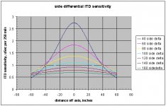
Next, let's look at the side differential ITD sensitivity.
Graph attached..this one is a little more difficult to understand..
Again, each line represents the distance the source is away from the listener plane, and the x axis represents the distance in inches off the listener's center of vision..
Didn't have time to correct the y axis units, so I modded the y axis title...y axis for this case represents the difference in arrival time, in uSec, for an x axis shift of 1/4 of an inch..I used 1/4 inch increments to keep this graph relatively centered in x..
Example...for a source 40 inches away, if the source moves 1/4 inch to either side, the ITD shift will be 2.75 uSec...for a 1 inch shift, it will be 4 times that, or 11 uSec.
If the source is 40 inches away, and 40 inches off axis, a shift right or left 1 inch will result in an ITD shift of 4 uSec.
If you look at the 160 inch numbers, center stage has an ITD sensitivity of about .7 times 4, or 2.8 uSec per inch sensitivity..if an object is moved 10 inches off axis here, the ITD shift will be about 28 uSec..
Application to hearing? If a virtual source has been generated which appears to be 160 inches away center line, an arrival time shift of 28 uSec at one ear will result in the virtual image moving about 10 inches to the side..
Application to speaker wires? Glad you asked..
To form a virtual image in space, both the time and intensity of the aural cues must be maintained true to source..given the complex waveform being presented to the speaker, how would a wire affect these? And, to what degree?. I can measure wires easily enough, but how does the measurement of the wires correlate to creation of a virtual soundstage?
Next, depth...
Cheers, John
Attachments
To form a virtual image in space, both the time and intensity of the aural cues must be maintained true to source..given the complex waveform being presented to the speaker, how would a wire affect these? And, to what degree?. I can measure wires easily enough, but how does the measurement of the wires correlate to creation of a virtual soundstage?
Would this actualy matter, so long as the cables to both speakers are the same, hence applying the same (if any) filtering to the sound signal , therefore keeping the relative "position" of the sound fixed?
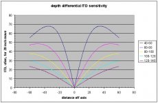
This graph is the sensitivity of ITD to depth...
Each line represents the difference in depth as a result of an ITD shift. For example, the blue line represents the difference in ITD from 40 inches away, to 60 inches away..
Note that on axis, the image is not sensitive to depth moves..in other words, if the source moves forward or back, ITD does not change.
If a source is 40 inches away, and 20 inches off axis, moving the source 20 inches away in depth causes an ITD shift of 52 uSec..
Look at the 120 numbers..if your speakers are presenting a virtual image 20 inches off axis, and one speaker, for whatever reason, delays the cue 10 uSec, the image will shift. I could say that it will shift back to 140 inches, a 20 inch move...but, I have kept the discussion simple here..in reality, the sensitivities to ITD and IID will interact, and that will be seen more as a smith chart than anything else...
I work to derive that chart, so that it will be plainly seen what a shift in either or both parameters will do to the aparrent location of the virtual source..
If one chooses to use the overly simplistic model of human hearing, that is, the JND research for monophonic discrimination of level sensitivity fro 20 to 20K, that is just fine...it, unfortunately, has nothing to do with soundstage parametrics..
Cheers, John
Attachments
Geeze, I'm typing as fast as I can....
Soongsc:I do not consider two speakers as adequate..nor, a dozen.
What we are doing with two speakers is attempt to fool the ears and brain into believing that a source is present in space in front of us..to do so, we manipulate ITD and IID. Unfortunately, since two speakers are present, each ear hears what was intended for the other...consequently, our brain has to filter out that inaccuracy in soundfield..
As for application to speaker wires? If one assumes only our sensitivity to monophonic reproduction, like THD, then it doesn't. But I am deriving the human sensitivyt to two sources, and the coherence between them.
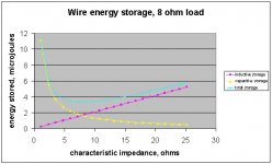
Between the amp and the speaker, resides an energy storage device, one with capacitance, inductance, and resistance. If you take a standard zip cord, with about 200 nH per foot inductance, the energy stored within the wire pair is about 4% of the total energy which resides in a 10Khz square wave at 8 ohms..cap energy, for this example, is trivially small...
The storage within the wire is lagging. A lagging mechanism will alter the ITD parameter.. for two identical wire sets, this lagging mechanism must affect the two channels in a different fashion..and that must be measurable..as is clear from the graphs, we are not looking for picosecond things, just low microsecond.. Once the measurement errors of current technology load resistors is removed, microsecond stuff is kinda trivial..but it ain't gonna be measured with dale 250 ni's...
BTW, the lagging storage mechanism of a transmission line...as it turns out, it is a minima when the line impedance matches the load..the simple il squared, and cv squared equations..Ok, I'll post that graph...this is a graph of an 8 ohm load, driven by a cable, to a 100 watt level..I believe (but am not sure) that I used a DC of 1, and a length of 10 feet. It's been over a year since I did that, and I'm hungry...
Cheers, I'm gonna go eat lunch...
John
Soongsc:I do not consider two speakers as adequate..nor, a dozen.
What we are doing with two speakers is attempt to fool the ears and brain into believing that a source is present in space in front of us..to do so, we manipulate ITD and IID. Unfortunately, since two speakers are present, each ear hears what was intended for the other...consequently, our brain has to filter out that inaccuracy in soundfield..
As for application to speaker wires? If one assumes only our sensitivity to monophonic reproduction, like THD, then it doesn't. But I am deriving the human sensitivyt to two sources, and the coherence between them.
Between the amp and the speaker, resides an energy storage device, one with capacitance, inductance, and resistance. If you take a standard zip cord, with about 200 nH per foot inductance, the energy stored within the wire pair is about 4% of the total energy which resides in a 10Khz square wave at 8 ohms..cap energy, for this example, is trivially small...
The storage within the wire is lagging. A lagging mechanism will alter the ITD parameter.. for two identical wire sets, this lagging mechanism must affect the two channels in a different fashion..and that must be measurable..as is clear from the graphs, we are not looking for picosecond things, just low microsecond.. Once the measurement errors of current technology load resistors is removed, microsecond stuff is kinda trivial..but it ain't gonna be measured with dale 250 ni's...
BTW, the lagging storage mechanism of a transmission line...as it turns out, it is a minima when the line impedance matches the load..the simple il squared, and cv squared equations..Ok, I'll post that graph...this is a graph of an 8 ohm load, driven by a cable, to a 100 watt level..I believe (but am not sure) that I used a DC of 1, and a length of 10 feet. It's been over a year since I did that, and I'm hungry...
Cheers, I'm gonna go eat lunch...
John
Attachments
Great stuff!
Even though I am an engineer (unsure about where my audio sensibilities lie?), I needed this page to help understand:
http://www.ibiblio.org/obp/electricCircuits/AC/AC_14.html
Even though I am an engineer (unsure about where my audio sensibilities lie?), I needed this page to help understand:
http://www.ibiblio.org/obp/electricCircuits/AC/AC_14.html
bigparsnip said:Would this actualy matter, so long as the cables to both speakers are the same, hence applying the same (if any) filtering to the sound signal , therefore keeping the relative "position" of the sound fixed?
You would think so...
What is the relation between the back EMF of the load, the load current, the amplifier damping factor through all four quadrants, the power supply loop coupling to the feedback (after the divider) and the transformer primary, and the high current signals within the chassis to the chassis ground loop formed by the input?
Answer: rather complex...and as I have pointed out, we actually are not measuring that stuff...
In reality, we need to go much farther with what we actually are sensitive to, to figure out how to measure speaker wire interactions within the system.
Luckily, I believe in measurements, not floob like "grain boundary" garbage...
Cheers, John
PS...a "quadrant" is the definition of what the amp output is doing..a pure resistance will cause the output stage to see only quadrant 1 and 3, 1 being positive voltage, positive current....3 being neg voltage and neg current..
Quadrants 2 and 4 are when the amp is driving a load which has stored energy...this is typical of what a speaker does to an amp, and this bends the load line, making the amp work harder..what is not considered, among other things, is what the amp damping factor is for the mid and higher frequencies when the amp is forced heavily into the even quadrants by low frequency content...and what the coupling to the input referenced ground is when the output draw switches quadrants, remember...there are two distinct capacitors, posrail and negrail, and they physically are not in the same location.....A-B's are considerably different from A's in that respect..(and, btw, tubes also...hint hint)
jneutron said:Geeze, I'm typing as fast as I can....
As for application to speaker wires? If one assumes only our sensitivity to monophonic reproduction, like THD, then it doesn't. But I am deriving the human sensitivyt to two sources, and the coherence between them.
John
In order to do that, you would need a mathematical human model that had been tested. What kind of model would satisfy that requirement?
What does ITD and IID stand for?
soongsc said:In order to do that, you would need a mathematical human model that had been tested. What kind of model would satisfy that requirement?
What does ITD and IID stand for?
Ah, first...ITD....Interaural Temporal Difference..the difference in time between receipt of the cue between ears..it has been tested and confirmed as human capable in the 1.5 to 2 uSec regime, depending on which researcher you choose..but they use some strange signals to test it..
IID is Interaural Intensity Difference..
Right now, I am calculating simply what point sources will produce w/r to ITD and IID when they are moved around within the soundstage area..as, this is what we are asking the two speaker system to reproduce..since our heads move, absolute terms are useless, we have to go to differential terms, this being the relative location of two or more sources in the field with respect to each other..
Once all this crunching is done, it will be possible to define what we need to be sensitive to in order to localize an image to some degree of certainty...for example, if one decides that we can localize to one foot, it is easy to back into the requirements for channel to channel ITD and IID accuracy..at the uSEc and dB level..
Measurement of exactly HOW sensitive we are will be measured by others better than I...I've been discussing this with some researcher types..for now, we can assume say, 1 foot of sensitivity, and calculate the system requirements from that..it'll be easy to change the system requirements once the relationships are understood and human testing provides some kind of envelope..but hey, a foot sounds reasonable to me..
Cheers, John
PS...note to all...yes, I know, it's a speaker wire thread...but, to discuss relevance, one needs limits of effects, no??
Interesting reading, jneutron, but I still would like to know what this has to do with speaker cables that are presumably the same for both channels.
Konnichiwa,
You measurements are based on the assumption that cables are purely linear devices which they are not.
It also assumes that measurements are relevant and correlate to "good sound", which is not the case.
In typhical stranded speaker cables you can measure the effect from copper oxide diodes with a very wide dynamic range spectrum analyser. Such measurements (using the Null Methode IIRC) by Ben Duncan on commercial cables published ages ago in HFN&RR) showed anything from -120 to around -70db for distortion in speaker cables.
I am not sure I follow. How do electrical parameters relate to money? And why are you talking about expensive cables?
I think you restate your question in a form that applies a certain logic and omits money. Money is strictly a market & marketing issue. Just because something is expensive has no direct bearing on it's quality.
If you wish to understand why certain physical/techincal etc. features in a given cable may (or may not) have an audible effect, you must ask questions that make sense in the context.
A few Pointers:
Most amplifier outputs have poor resilience to RFI, noise returns to the input stage through the feedback loop unattenuated and there can intermodulate with the signal. Speaker Cables can make excellent aerials.
RFI Demodulation in stranded cable with copper oxide layers present may cause all sorts of mischief as well.
Both of the above are Cable/Amplifier interactions, analysing the cable seperate from the Amplifier is not going to help.
Equally, other "secondary" and "tertiary" effects may raise their heads. Excessessively low inductance cable tends to be high capacitance and many commercial amplifiers are marginally stable into such loads, often bursting into oscillation, sometimes merely on signal peaks.
Anyway, the problem is one of complex interactions, simplistic, reductionist methodes are not going help the understanding, as the problems are systematic in complex systems.
Sayonara
MikeG said:Before hooking up my speakers I tested a bunch of cables from bell wire (yes, solid core 0.6mm) through to QED OFC cable (sorry don't have a part number, borrowed it) on a Wayne Kerr Bridge Analyser, which is good to the last nH and mOhm. The results suggest that the only impedance large enough to have a significant effect is resistance, and that the resistance is exactly what you'd expect it to be given the cross sectional area of the conductor, from d.c. to 30kHz.
You measurements are based on the assumption that cables are purely linear devices which they are not.
It also assumes that measurements are relevant and correlate to "good sound", which is not the case.
In typhical stranded speaker cables you can measure the effect from copper oxide diodes with a very wide dynamic range spectrum analyser. Such measurements (using the Null Methode IIRC) by Ben Duncan on commercial cables published ages ago in HFN&RR) showed anything from -120 to around -70db for distortion in speaker cables.
MikeG said:What I'd like is for the *engineers* out there to explain what it is about their expensive cable, in electrical terms, that made it worth the money?
I am not sure I follow. How do electrical parameters relate to money? And why are you talking about expensive cables?
I think you restate your question in a form that applies a certain logic and omits money. Money is strictly a market & marketing issue. Just because something is expensive has no direct bearing on it's quality.
If you wish to understand why certain physical/techincal etc. features in a given cable may (or may not) have an audible effect, you must ask questions that make sense in the context.
A few Pointers:
Most amplifier outputs have poor resilience to RFI, noise returns to the input stage through the feedback loop unattenuated and there can intermodulate with the signal. Speaker Cables can make excellent aerials.
RFI Demodulation in stranded cable with copper oxide layers present may cause all sorts of mischief as well.
Both of the above are Cable/Amplifier interactions, analysing the cable seperate from the Amplifier is not going to help.
Equally, other "secondary" and "tertiary" effects may raise their heads. Excessessively low inductance cable tends to be high capacitance and many commercial amplifiers are marginally stable into such loads, often bursting into oscillation, sometimes merely on signal peaks.
Anyway, the problem is one of complex interactions, simplistic, reductionist methodes are not going help the understanding, as the problems are systematic in complex systems.
Sayonara
Thorsten
As this is a thread that was started to discuss measured results, do you have any hard data on the amplitude of these effects?
As this is a thread that was started to discuss measured results, do you have any hard data on the amplitude of these effects?
Konnichiwa,
As stated, the distortion measurements done in HFN & RR showed comparably high levels of distortion in some cables, I do not have the article handy, I remember as much as -70db in some cables, testing via null methode and using complex signals, there was no direct HD but clearly complex IMD involved.
For RFI Effects numbers are impossible, as are they for amlifier stability etc. The numbers are highly dependent on the exact configuration, but getting radio reception of Radio Kreplakistahn or such via RFI ingress from the Speaker Cables are not unheard off (I had cases like that myself, ultimatly tracable to speaker cables - clip on ferrites on them fixed it), that implies full demodulation of AM signals in the Amplifiers input stage.
Equally, in my repair/modification work I have come across many marginally stable amplifiers, some will not oscillate into 1uF or even 100nF but will show burst oscillation with a feww 100pF to a few nF.
As stated, it is a HIGHLY complex subject, attempting to dumb it down to single numbers is unhelpfull at the very least.
Sayonara
pinkmouse said:As this is a thread that was started to discuss measured results, do you have any hard data on the amplitude of these effects?
As stated, the distortion measurements done in HFN & RR showed comparably high levels of distortion in some cables, I do not have the article handy, I remember as much as -70db in some cables, testing via null methode and using complex signals, there was no direct HD but clearly complex IMD involved.
For RFI Effects numbers are impossible, as are they for amlifier stability etc. The numbers are highly dependent on the exact configuration, but getting radio reception of Radio Kreplakistahn or such via RFI ingress from the Speaker Cables are not unheard off (I had cases like that myself, ultimatly tracable to speaker cables - clip on ferrites on them fixed it), that implies full demodulation of AM signals in the Amplifiers input stage.
Equally, in my repair/modification work I have come across many marginally stable amplifiers, some will not oscillate into 1uF or even 100nF but will show burst oscillation with a feww 100pF to a few nF.
As stated, it is a HIGHLY complex subject, attempting to dumb it down to single numbers is unhelpfull at the very least.
Sayonara
The problem you get into here is that even if you measure differences there is no correlation between measured differences and subjectively perceived differences in sound quality.
The objectivists will point out the similarity of measurements and the subjectivists will always say "you're not measuring the right things" because they hear (or think they hear) a difference. Subjectivists will remain subjectivists. Objectivists will remain objectivists.
This is another reason why engineers don't spend a lot of time considering such matters. There are REAL problems out there that CAN be solved.
Someone asked where I stand. Well, I wouldn't spend a more than about $0.50 per foot for speaker wire, and it would have to look pretty nice to justify $0.50 per foot.
I_F
Kuei Yang Wang said:As stated, it is a HIGHLY complex subject, attempting to dumb it down to single numbers is unhelpfull at the very least.
Yes, but it should be measurable for a simple case of one amp and two cables, as would occur in a simple ABX test.
jneutron said:[snip] Without consideration of those parameters, it is not possible to determine the effect on the virtual soundstage of the parameters R, L, C, and Q of the speaker wires. (it is not possible to determine level of effect, if you don't know how we hear).[snip]Cheers, John
Oh yes it is. Being aware of the normal variation in all involved components (speaker, xover, air temp, whatever) it is perfectly realistic to say that if the speaker cables make up say 5% of the values of the other parts of the system (R, C, L), their influence can be safely disregarded.
So, it is rather useless to take off on a treatise of how we hear, it would be usefull to show how cable variables could influence the total system variables. But I don't expect that to happen. Any other 'engineers' out there?
Jan Didden
Bill Fitzpatrick said:Interesting reading, jneutron, but I still would like to know what this has to do with speaker cables that are presumably the same for both channels.
The signals, the current, the current slew rate, voltage, voltage slew rate, and energy stored in each cable is different...assuming a stereo signal, of course.
A simple example...
Assume a human voice presented binaurally, as being 100 inches away, 40 inches off axis right...this requires a specific ITD and IID. Let's assume that the speakers, while wildy reactive, are relatively equal w/r to freq response..
What level of IID will shift the voice a foot to the back, or to the left, or right..what level of ITD?.
Will the inductance of the cable shift all frequencies the same amount? IOW, if I put 2 uH in series, will all frequencies shift the same amount temporally, and do all frequencies have equal attenuation? Or, is the source of higher frequency content going to shift relative to the fundamentals??
If I tell you we can detect 1 uSec ITD's, and .01 dB IID's differentially, for non correlating sounds that are below 5 dB difference in intensity.....speaker wires can be easily tested within those constraints...
Problem is, what are the constraints...
Think of ITD and IID in terms of a "smith chart"..it is possible to plot constant ITD, and it is possible to plot constant IID. The gradient lines on that chart represent the differences, and by defining how much of a difference, allows us to back into what the electrical numbers are..
Once I have all the IID numbers, I'll be able to construct such a chart, and then the electricals to be measured...
Cheers, John
- Status
- Not open for further replies.
- Home
- General Interest
- Everything Else
- Technical discussion on loudspeaker cable