The good news is the error can be compensated 😉
That's not good news...
Just to be clear, this is Bit 8 ONLY switching, not LSB and other bits switches off and Bit 8 switching on and Back?
Yes you are right, I forgot about it. Compensation works only at the DEM decoupling pins, i.e. bit #10 to bit #15. It does not work for bit #9 either.
We have to accept that R1 chips are what they are.
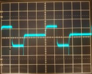
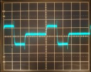
Bit #8 switching:
0000000001111111 (12 samples)
0000000010000000 (24 samples)
0000000010000001 (12 samples)
repeating ad infinitum.
We have to accept that R1 chips are what they are.
Bit #8 switching:
0000000001111111 (12 samples)
0000000010000000 (24 samples)
0000000010000001 (12 samples)
repeating ad infinitum.
HSH8836 from an old Marantz board.Is your TDA1541A R1 chip date coded 8740. From Pedja?
Excuse me, I was blind (You have photo with testbed). I really appreciate what you do.
if you want to test some different R1 grade chips give me posting instructions in PM.
volli
if you want to test some different R1 grade chips give me posting instructions in PM.
volli
Last edited:
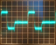
Allow me to translate for the hoi polloi (e.g. me) who are a bit thick and slow.Bit #8 switching:
0000000001111111 (12 samples)
0000000010000000 (24 samples)
0000000010000001 (12 samples)
repeating ad infinitum.
We take, in the post with many pictures, each given bit and switch the data +/- 1 LSB around this bit being on.
So normally we expect clean step of +/- 1LSB.
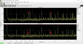
For whatever reason, we have two bits that show a behavior that is erroneous.
Now, to me this almost looks like a defective die.
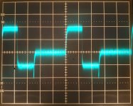
As if somehow the LSB's in one bit are partially and in the other near completely shunted away. Maybe a bit switch being triggered erroneous?
Like here, I may be wrong, that looks like the LSB trying to switch to add to the bit and failing to turn on?
And here:
The glitch is almost as high as the LSB should be, but it is clamped by something else.
I'm not an IC specialist, but to me this doesn't look like "differential nonlinearity" but bad silicon.
It may have been graded R1 with a small defect (someone barfed on the wafer in the Monday morning shift and didn't quite wipe the wafer clean enough) that over time turned into a hard fault.
Anything affecting not the LSB would have probably been permanently recycled.
I'd be interested how a good normal (not relaxed spec) new or lightly used chip looks like.
Thor
Last edited:
Thing is, desoldering CAN (not saying it did here) degrade chips as well. And this is desoldered one. Rare chips that are trough hole, should be removed by cut and abrasives method.
Yes, but not all desoldering is the same, as said it can, not it will. And it may or may have not damaged the chip, or simply it was a bad one off. The issue is, how audible is, and how many will buy R1 or badly desoldered ones and encounter the issue (most don't have measuring gear).
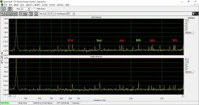
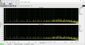
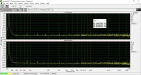
The interesting thing is that the error does not show up in full scale test. The THD is still 0.0005% in both channels.I'm not an IC specialist, but to me this doesn't look like "differential nonlinearity" but bad silicon.
It may have been graded R1 with a small defect (someone barfed on the wafer in the Monday morning shift and didn't quite wipe the wafer clean enough) that over time turned into a hard fault.
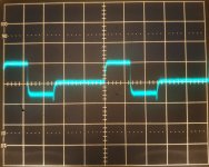
Anyway, what we could see here is 1 LSB error, i.e. within spec. Monotonicity is still maintained.
The attached picture is 1/2 LSB error (bit #8, plain chip).
Attachments

I added the offset part to my little test board, Right channel. It is interesting, the 2nd, 4th, etc. harmonics can be nulled out at low level (-60 dB). There was no measurable difference at high level. I measured about 50 mV offset, but this is not very sensitive.
I don't know how audible is this.
Attachments
Yes, but not all desoldering is the same, as said it can, not it will. And it may or may have not damaged the chip, or simply it was a bad one off.
Bipolar IC's are surprisingly resilient.
These days they are still used in rad hardened applications.
Now "MOS" IC are another story.
I remember the days when looking at a MOS IC crosseyed would damage it and the anti-static handling precautions prescriped were insane.
These days MOS IC's are pretty rugged, at least in terms of electrostatic damage. Radiation is still an issue.
Thor
Last edited:
... and I know why and how it works. Voltage on the + input of the opamp 45.5 mV.
Attachments
Last edited:
Can you try 3.3...10nF from AOL/AOR to dgnd?. and I know why and how it works. Voltage on the + input of the opamp 45.5 mV.
You mean AOL/AOR to AGND? I added 4.7 nF between the + and - input of the opamp, it did not make any difference. L ch without capacitor, R ch with capacitor. -60 dB and 0 dB. Gain reduced by 10 dB at full scale measurement, to avoid overloading of the soundcard. The glitch amplitude did not change, either.
Attachments
Last edited:
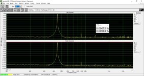
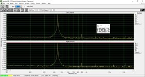
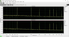
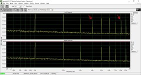
Here is the spectrum of the stepped test signal (like in post #95). Upper (L ch): uncompensated, lower (R ch): 46 mV offset on the + input of the opamp. There is nothing to compensate up to bit #5. Glitch occurs from bit #6 and up, the glitch amplitude (and energy) is increasing at higher bits. The spectrum line at 4 kHz and 8 kHz is the indication of glitch. Attached is bit #0 with no visible glitch and bit #15 where I could sharply null out the 4 kHz spectrum line in the R channel.
Attachments
You mean AOL/AOR to AGND? I added 4.7 nF between the + and - input of the opamp, it did not make any difference.
Ok.
L ch without capacitor, R ch with capacitor. -60 dB and 0 dB.
The lower trace looks a little cleaner, is that "with" capacitor?
Attached is bit #0 with no visible glitch and bit #15 where I could sharply null out the 4 kHz spectrum line in the R channel.
Just to be clear again, Bit 15 -> MSB and Bit 0 = LSB?
I really wish you could use standard terminology that doesn't need interpretation.
Thor
- Home
- Source & Line
- Digital Line Level
- TDA1541A reducing DNL