Good to know that the front bit is a foam gasket too.
I believe the gasket is 6mm-ish tall. So if it compresses to 1mm, I will loose 5mm x 73mm (diam) volume in the front chamber. That introduces a big peak in the simulated response.
xrk971: In your view, what's the ideal shape of the midrange drivers response pre-crossover?
Yesterday I played with the ABEC model again. I now have a 1cm deep 73mm (diam) wide cavity before the frustum. To print without supports (no overhangs), I tried making it a frustum in itself with 45 degree walls. However, this has the effect of reducing the volume, and introduces the peak close to the cut-off due to the CD reflection. Increasing the depth of the frustum into the horn doesn't really help for some reason.
Any chance you could sim the driver in one of your ABEC models and see what kind of throat distance / front chamber would work well as a cross-check?
I am also wondering if perhaps the holes should be moved slightly closer to the horn throat (86mm now), providing some overlap beyond the crossover frequency. This will also make the adapter smaller, but will also bring the holes more into view from the CD's perspective. Right now they cause a resonance at ca. 750hz. Of course, with a crossover at 12-1300Hz and a notch filter I don't think that would be an issue, even if they are slighly closer.
I'm at work now, but when I'm at home I can illustrate this with some drawings, to make it clearer.
The gasket on the front is not foam, its rubber and quite hard.
So don't expect it to compress more than 1mm
So don't expect it to compress more than 1mm
Thanks. Are you able to provide a profile, including the surround and rubber gasket?
Sent from my iPhone using Tapatalk
Sent from my iPhone using Tapatalk
The gasket on the front is not foam, its rubber and quite hard.
So don't expect it to compress more than 1mm
ditto
Ideally, the response of the mid driver should be flat through the XO frequency and extend 1 octave above. So for 1khz should not fall off until 2khz. However that is often difficult to achieve in which case we often set the XO freq to coincide with the -3dB point of the falloff.
Ideally, the response of the mid driver should be flat through the XO frequency and extend 1 octave above. So for 1khz should not fall off until 2khz. However that is often difficult to achieve in which case we often set the XO freq to coincide with the -3dB point of the falloff.
Were you answering a question I missed?
I wouldn't say difficult but nearly impossible, especially on a wide horn, given the cancellation null due to the reflection from the diaphragm of the CD. So what I think one should do instead is to try to make the acoustic roll off of the mids mirror the acoustic roll off of the CD around the crossover point, by tuning the bandpass chamber and the mid entry point, which is more easily said than done, so one ends up with what you said.
I've heard others advise to crossover at/just before the null which does give you an acoustic roll off not due to bandpass. Then you want/need the bandpass effect to kick in to prevent the mid response from rising too far above the null. With DSP you can work around the lack of bandpass acoustic lowpass but then you don't get the benefit of attenuating distortion products.....
I tried running the 3F322 instead of the 3F25 in the model. Surprisingly there was very little difference. I think it´s related to the throat entry distance. Resolving at 10mm closer to the throat now, and will check again.
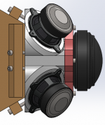
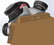
Anyway, I added a variant for mounting the adapter to the horn - again relying on inserts. Ugly but I need to be realistic about what I can achieve with plywood. 🙂
Hopefully with eight M6 screws the tension on the plastic won´t be too high.


Anyway, I added a variant for mounting the adapter to the horn - again relying on inserts. Ugly but I need to be realistic about what I can achieve with plywood. 🙂
Hopefully with eight M6 screws the tension on the plastic won´t be too high.
Attachments
Hi JCX:
You already see its not that easy. How much is your time worth?
My question was whether the state of the art had progressed to the point where someone could simply download the horn to a 3D printer ala the old Startrek matter synthesizer. When this is a reality for mainstream objects, changes will ripple throughout the economy.
I also wonder if one could do a 3D scan of a waveguide and print a copy out and, if so, would it be rugged enough for a one-off design. A 3DMonster machine that can print 18" cube is just over $4K. Probably would take a very long time to print...
Which of these free 3D CAD tools is worth learning? I've downloade 123D and FreeCAD but have barely had time to turn them on. I can do Sketchup but it looks like the hard way to do waveguides.
Jack
I spent countless hours trying to scan waveguides.
It was a total disaster.
The problem was that the surface has to be perfectly smooth. I wound up with a lot of weird geometry problems that had to be fixed by hand.
Basically, it was faster to create a new waveguide in 123D than scan an existing one.
I could see how 3D scanning would be good for complex shapes. But I can make a simple waveguide in 3D in fifteen minutes. I spent a whole day trying to scan one.
Were you answering a question I missed?
I wouldn't say difficult but nearly impossible, especially on a wide horn, given the cancellation null due to the reflection from the diaphragm of the CD. So what I think one should do instead is to try to make the acoustic roll off of the mids mirror the acoustic roll off of the CD around the crossover point, by tuning the bandpass chamber and the mid entry point, which is more easily said than done, so one ends up with what you said.
I've heard others advise to crossover at/just before the null which does give you an acoustic roll off not due to bandpass. Then you want/need the bandpass effect to kick in to prevent the mid response from rising too far above the null. With DSP you can work around the lack of bandpass acoustic lowpass but then you don't get the benefit of attenuating distortion products.....
Cookemonster asked this:
xrk971: In your view, what's the ideal shape of the midrange drivers response pre-crossover?
Hence my response.
I tried running the 3F322 instead of the 3F25 in the model. Surprisingly there was very little difference. I think it´s related to the throat entry distance. Resolving at 10mm closer to the throat now, and will check again.
Anyway, I added a variant for mounting the adapter to the horn - again relying on inserts. Ugly but I need to be realistic about what I can achieve with plywood. 🙂
Hopefully with eight M6 screws the tension on the plastic won´t be too high.
You could also just epoxy the plastic 3d assembly to the wooden horn. I am not sure they need to be separable unless you want to try different throat assemblies.
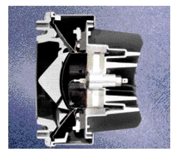
Well this is the profile i drew up quite some time ago for the 3fe25.
I cut a paper until i was happy with the fit then measured that.
But the front gasket is missing.

I cut a paper until i was happy with the fit then measured that.
But the front gasket is missing.
Cookemonster asked this:
Hence my response.
Right, and if I had turned back one page I would have seen that myself...
My opinion is coming from trying to do a 90x45 horn as a 2-way with a big driver. I'm getting more acoustic roll off than I want; have to use a phase plug to minimize it. I still have to cross over between 900 and 1000 hz. To do that, i need perhaps a 4th order high pass on the CD to protect it, which is good because I'm getting a fairly sharp acoustic roll off on the mid and so the slopes match fairly well. In the several iterations I've done, I get a fair acoustic crossover without any DSP or passive components, just playing both drivers together to get a measurement for the crossover.
I'll warrant it will be a very different set of tradeoff is CM's 3-way 60x60 horn. Where you can get lots of overlap will be between his mids and his woofers and there I would agree with you completely. But I still think the mid-CD crossover is going to be up against the reflection null with more overlap than I have but nowhere near a full octave. I'm not trying to be argumentative; discussion helps understanding.
I spent countless hours trying to scan waveguides.
It was a total disaster.
The problem was that the surface has to be perfectly smooth. I wound up with a lot of weird geometry problems that had to be fixed by hand.
Basically, it was faster to create a new waveguide in 123D than scan an existing one.
I could see how 3D scanning would be good for complex shapes. But I can make a simple waveguide in 3D in fifteen minutes. I spent a whole day trying to scan one.
If you can create a wavequide shape in 123D in less than an hour, then the tool must be worth learning.
Any regrets now on having bought a low end printer?
What do you think about scanning a driver to make a form/fit model for the CAD drawing of the speaker/horn?
Thanks,
Jack
Right, and if I had turned back one page I would have seen that myself...
My opinion is coming from trying to do a 90x45 horn as a 2-way with a big driver. I'm getting more acoustic roll off than I want; have to use a phase plug to minimize it. I still have to cross over between 900 and 1000 hz. To do that, i need perhaps a 4th order high pass on the CD to protect it, which is good because I'm getting a fairly sharp acoustic roll off on the mid and so the slopes match fairly well. In the several iterations I've done, I get a fair acoustic crossover without any DSP or passive components, just playing both drivers together to get a measurement for the crossover.
I'll warrant it will be a very different set of tradeoff is CM's 3-way 60x60 horn. Where you can get lots of overlap will be between his mids and his woofers and there I would agree with you completely. But I still think the mid-CD crossover is going to be up against the reflection null with more overlap than I have but nowhere near a full octave. I'm not trying to be argumentative; discussion helps understanding.
I have hit the acoustic falloff at where my electrical XO is at before and if the slopes are similar it ends up working pretty good. You just have to account for the additional falloff slope of you want to get the phase flat.
I had some strange resonances showing up, and also wanted to simulate better the effect of a phase plug. In the previous model, everything about the midranges outside the entry hole to the horn was done in the LEM part, so similar calculations as Akabak provides.
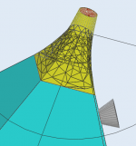
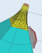
Thanks Nissep for the cone profile. Here´s how the driver is added into the BEM part of the model:


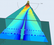
Rear chamber still in the LEM section. As you can see above, I have tried to use a kind of phase plug to increase the high frequency response.
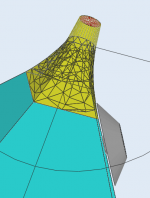
A sound field at 2000Hz shows clearly the kind of assymetry one can expect when loading only one driver into a Synergy horn.

Or at 1400Hz:

Next - add the three more drivers, and re-sim with reasonable front chambers.
Thanks Nissep for the cone profile. Here´s how the driver is added into the BEM part of the model:
Rear chamber still in the LEM section. As you can see above, I have tried to use a kind of phase plug to increase the high frequency response.
A sound field at 2000Hz shows clearly the kind of assymetry one can expect when loading only one driver into a Synergy horn.
Or at 1400Hz:
Next - add the three more drivers, and re-sim with reasonable front chambers.
Attachments
-
 2015-01-31 18_44_25-ABEC3 - ABEC Synergy7.png55.5 KB · Views: 672
 -
 2015-01-31 18_44_40-ABEC3 - ABEC Synergy7.png56.6 KB · Views: 652
 -
 2015-01-31 18_45_26-ABEC3 - ABEC Synergy7.png64 KB · Views: 656
 -
 2015-01-31 18_45_38-ABEC3 - ABEC Synergy7.png66.2 KB · Views: 647
 -
 2015-01-31 23_16_38-ABEC3 - ABEC Synergy7.png49.5 KB · Views: 666
 -
 2015-01-31 23_25_52-ABEC3 - ABEC Synergy7.png73.8 KB · Views: 666
Your welcome.
As i said once before i have started to sketch on a phase plug.
And i made a 3d print of the profile. It is close enough.
As i said once before i have started to sketch on a phase plug.
An externally hosted image should be here but it was not working when we last tested it.
And i made a 3d print of the profile. It is close enough.
An externally hosted image should be here but it was not working when we last tested it.
Sorry! Yes you did say that. I forgot.
It´s a bit advanced for me to model in ABEC now, but did you test or sim this phase plug design? For instance, how did you arrive at the exit hole diameter?
With the simple design I´m simming now, I end up with a huge peak around 1500Hz (when simmed without the horn, just the compression chamber into free air).
I have not simulated that phase plug.
I thought that was your job..
I focused on keeping the path length equal.
And tried to copy JBL..
When I chose 10mm as my entry hole I drilled different holes in a 3mm thick plate, attached the driver centered over the hole and measured the response.

10mm might be a good compromise between obstructing the compression drivers respons and the performance of midrange. (at least i think so)
As long as I don't feed the midrange with to much power I think it`s big enough.
This is 10mm port with minimal closed back chamber made from mailing tube.

And this is 12mm.

I have not measured anything on a horn yet.
But I made a sim in Hornresp at leased.


I thought that was your job..
I focused on keeping the path length equal.
And tried to copy JBL..
When I chose 10mm as my entry hole I drilled different holes in a 3mm thick plate, attached the driver centered over the hole and measured the response.
10mm might be a good compromise between obstructing the compression drivers respons and the performance of midrange. (at least i think so)
As long as I don't feed the midrange with to much power I think it`s big enough.
This is 10mm port with minimal closed back chamber made from mailing tube.
And this is 12mm.
I have not measured anything on a horn yet.
But I made a sim in Hornresp at leased.
Nissep,
Thanks a lot.
Right now, I cannot seem to make the simulated driver in BEM mode match your results. I get a huge peak around 1000Hz. I think calibrating to your measurements is necessary before trying out various phase plug variations. Perhaps the simulation exaggerates the peaks somehow (assumes no cone flex etc), but I think I should be close first...
- Status
- Not open for further replies.
- Home
- Loudspeakers
- Multi-Way
- Synergy horn - 3d printing entry?