Hi cookiemonster,
i'm sorry that I don't have the time to help you with the ABEC part, extremely busy work time for me me, which is à shame cause I really would like to help you more. One tip; use absorbtion in ABEC with à very small value like 0.01 to 0,1, this Will help take the extreme peaks in the sim more to the real world values. Use absorbtion one every part of the sim (throat, horn, mid chamber etc.) because in the real world no material is 100 percent stiff and smooth.
As Said I don't have much time but I do read this forum now and then so of you have any questions I love to help out because you're doing very well already and I would like to help you get there!
If you can create a wavequide shape in 123D in less than an hour, then the tool must be worth learning.
123D is easy to learn, and it's fast.
I'm starting to realize that it's simplicity is a double-edged sword. For instance, I haven't been able to figure out a way to mirror a shape. It is also very slow; I have six cores and 16gb of ram, which is fairly powerful I think. And 123D slows down a LOT. I've noticed it's faster on my laptop, so it may 'prefer' Intel over AMD for some reason.
By far my biggest gripe with 123D is that it's buggy as hell. I worked about eight hours yesterday on a waveguide, and it easily crashed five times. I can't think of another software package that crashes so much.
I'm thinking about buying Rhino, or maybe going back to Blender.
Any regrets now on having bought a low end printer?
I'm actually starting to like the thing. Here's a few things I like about it:
1) I've noticed that I barely go in the garage any more. I used to spend a LOT of time in the garage; now I barely go in there. My friend Jon Whitledge clued me in to this idea. I was talking to Jon about the Magic Bus, and wondering if he spent a lot of time in the garage doing fabrication. Jon said that the basically does everything in 3D, and then he has the pieces fabricated for him by pros. This was kind of a revelation, because I've always tried to fabricate things out of wood, by hand. Both of us live in San Diego, and a garage is a real luxury here. I'd estimate that I spend about $500 a month extra to have a garage. (Due to the outrageous cost of real estate here.)
What do you think about scanning a driver to make a form/fit model for the CAD drawing of the speaker/horn?
Thanks,
Jack
I'm not a fan of 3D scanning. I've been able to get exceptional results with a simply ruler. Here's an example of what I mean:
In my latest waveguide, the tolerances are so tight, I can 'press fit' the drivers and they'll stay put... without bolts or screws.
Now, obviously you wouldn't want to run them that way full-time, but the idea that the tolerances are so tight, everything just fits together like a jigsaw puzzle, is remarkable.
Last edited:
I can't figure out hard dimensioning in 123d - and I haven't found any written doc - dozens of hours of youtube demo/tutorials doesn't do it for me when I have 1/2 a century investment in reading
fusion 360 seems to be the pro evolution of the same annoying interface - I suppose you could call yourself a startup for the free 1 year access to the full 3d version
fusion 360 seems to be the pro evolution of the same annoying interface - I suppose you could call yourself a startup for the free 1 year access to the full 3d version
I hate to throw a wet blanket on all of this, but here's a few things I've found:
1) The measured difference between a frustrum and a proper phase plug is minimal. You *might* be able to extend the high frequency cutoff by 10%, but that's about it. You're not going to get another octave, or even half of an octave.
2) The biggest improvement that I see with a phase plug is the rolloff. For instance, without a phase plug, the response in the octaves from 1500hz to 6khz has peaks and dips in it. When you add a phase plug, the peaks and dips are smoothed out.
I think that one of the reasons that the phase plug doesn't make a huge difference is the pathlength difference between the midrange taps. For instance, in a Danley SH-50 the midrange taps are something like 10cm apart. If we want to give our sources within one quarter wavelength of each other, then that 10cm gap means that the upper limit of our midranges is 850hz.
The acoustic xover on the Danley SH-50 is right around 850hz, so I think that the spacing of the midrange taps likely plays a larger role in the high frequency limit than what the phase plug on the midranges looks like.
Again, I kinda feel like I'm being a bummer here, and I'm not trying to do that. The good news is that you *can* increase the cutoff to 1500hz or even 2khz if you opt for a smaller midrange. Which is why I use 2" and 3" drivers.
Did you guys see the measurements I posted of a 3D printed Paraline? I think that holds promise. One way to simplify a Synergy horn is to use more compression drivers, to lower the xover, instead of using smaller midranges to *raise* the xover. The Paraline is a strange beast, but it allows you to constructively combine compression drivers in the octave from 1-2khz.
I can't figure out hard dimensioning in 123d - and I haven't found any written doc - dozens of hours of youtube demo/tutorials doesn't do it for me when I have 1/2 a century investment in reading
fusion 360 seems to be the pro evolution of the same annoying interface - I suppose you could call yourself a startup for the free 1 year access to the full 3d version
I'm not sure what hard dimensioning is.
I am getting parts out of my 3D printer that are accurate to a fraction of a millimeter. In fact, the only reason that the accuracy isn't higher is that the PLA shrinks! But I'm working on that too. (Hint: you can make structures in 3D that are difficult/impossible any other way. The walls of my new waveguide are honeycomb, to reduce shrinkage. I'm also trying to figure out how to do three dimensional honeycomb.)
The 'ruler' tool in 123D is handy also. For instance, when making the holes for the midrange frame, I can measure the frame perfectly, then compare it to the Peerless spec sheet.
@Kessito: Thank you! I had read about the damping WallImpedance, but I think I have tried just about everything else instead. 🙂
Let me show how it changed the response. This is the driver with a small cylinder on top (few mms), a cap and a hole in the cap of 10mm across - trying to mimic Nissep´s measuring setup.
Before adding damping:

After adding damping:

And here the only thing dampened is the cylinder walls (factor 0.1). Not the driver, nor the cap.
Thanks again! Any rules of thumb on various materials? 🙂
Let me show how it changed the response. This is the driver with a small cylinder on top (few mms), a cap and a hole in the cap of 10mm across - trying to mimic Nissep´s measuring setup.
Before adding damping:
After adding damping:
And here the only thing dampened is the cylinder walls (factor 0.1). Not the driver, nor the cap.
Thanks again! Any rules of thumb on various materials? 🙂
Attachments
![2015-02-01 20_52_00-VacsViewer - (new) - [SPL - Copy].png](/community/data/attachments/419/419776-979b333d7febad7e564641fdbd3410f6.jpg?hash=l5szPX_rrX)
![2015-02-01 20_52_19-VacsViewer - (new) - [SPL].png](/community/data/attachments/419/419784-c0330b394e93e0203ae6fc4297c2d73b.jpg?hash=wDMLOU6T4C)
I think mech CAD needs to be able to drive dimensions, offsets, angles, tangent with actual numbers entered from a keypad, contours from equations or at least csv, vector or spline imports
rather than drag and drop, nudge and hope
maybe the cute interface is just hiding the capability from me
the way I tried "magnetic" snap is a fail for finding tangents to curves - the attraction algorithm is nonlinear, I don't see how to constrain it to only move objects along a axis or in a plane until surfaces/edges contact
its not like I can't run CAD sw that does meet my expectations:
PTC Creo Element free version - does want a connection so PTC can authorize each session
Attachments

Last edited:
I think that one of the reasons that the phase plug doesn't make a huge difference is the pathlength difference between the midrange taps. For instance, in a Danley SH-50 the midrange taps are something like 10cm apart. If we want to give our sources within one quarter wavelength of each other, then that 10cm gap means that the upper limit of our midranges is 850hz.
I am not quite sure I follow this one. Wouldn´t this apply mostly if you wanted to measure the SPL in the midpoint between all the mid entry holes, where the sounds waves certainly will cancel out if they are 1/4 away from eachother. Once you move a meter away, the real distance between the midrange holes is negligible I suppose.
You recently draw a picture in one of your other threads where you argued along the same lines (monster massive?). I don´t see why that doesn´t apply in this case?
As I understand it, this is how it works:
We have a couple of sources on the Synergy horn. Those sources are spaced a certain distance apart. In the case of the midranges, the two sources are spaced about 10cm apart.
Due to that spacing, we'll have the following interactions:
1) At one wavelength (3400hz), the sources will combine constructively.
2) At 1/2 wl (1700hz), the sources will null each other out
Below one half wavelength, they'll begin to sum constructively. By the time you reach 1/4 wl (850hz), the midranges are in-phase.
At this point, someone is going to say, "what are you talking about Bateman? The midranges aren't 10cm apart. They're nearly a foot apart."
That's true, but the wave doesn't form until in enters the waveguide. Until the air hits the waveguide, it might as well be a liquid. The dimensions are too small for the wave to form.
So far all intents and purposes, the source of the sound is the midrange taps.
TLDR: a phase plug won't do a whole lot to extend the high frequency response. The use of small midranges WILL, because it allows you to physically cram them together very tightly. Taken to the extreme, you end up with something like the design I posted in "JBL M2 for the poors"
By the way, you can hear this for yourself. Go rent an SH-50. As Danley has noted himself, the source of the sound is neither the mouth of the SH-50, nor the throat. The source of the sound seems to be hard to determine. When I had the SH-50s in my house, there was an eleven year old sitting two feet from one of the SH-50s. She once asked me if it was on. The location of the sound is so vague, even a little kid can tell there's something funky going on. The sound does not seem to emanate from the loudspeaker. (Basically I had Monster Massive *and* the SH-50s sitting side by side, and she couldn't tell which was playing, despite being just two feet away. And it was playing LOUD.)
Last edited:
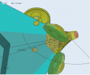
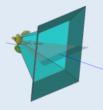
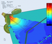
Current sim with Faital 3FE25, in a simple chamber that should be easy enough to both print and/or do with regular tools. 🙂 Rear chamber simmed in LEM part - 0.3 liters.


You can see how it peaks slightly above 1kHz, and that -3dB from the flat section is around 1.5kHz. The peak is rounder thanks to Kessito´s tip on using damping to get more realistic results - not assuming perfectly reflective surfaces, but allowing some absorbtion.
All four mids are now in the BEM part of the model, except the rear chambers, which are simulated as a simple enclosure in the LEM section.


Raw response of each driver 90-92dB efficiency (peak values) 1m from horn mouth compared to around 85db at 1m from driver (also peak values) in the bandpass alone.

Adding a LR2 filter @ 1300Hz:

Here´s the difference in amplitude response between the single bandpass driver and the same bandpass driver in the horn. The absolute levels is off, since it´s measured at different distances, but if we assume the top flat part is regular horn loading, I think can explain drop from ca 1150Hz as the reflection from the throat.
It appears to me that since the -3dB level of the bandpass driver by itself is around 1500Hz, it should be possible to get more extension by moving the mids even closer.

Naturally, moving the mids closer brings them more into the view of the compression driver, and the holes will be relatively bigger compared to the throat area there.
So the question is whether the response now is OK - can the DE250 cross over at this level in a domestic environment without strain? I should think so, but please correct me if i´m wrong.
I would tend to think that for maximum output, and less regard for fidelity, one would move the holes slightly closer to the compression driver, but for home use it´s best to leave them where they are. Any inputs?
PS: Only the mid chambers have had damping added to them. Next time I run the solver I will add some damping to the horn, QTWG etc.
Added:
Here´s field showing the frequency with maximum cancellation. You can see high SPLs near the compression driver but very low travelling towards the mouth.

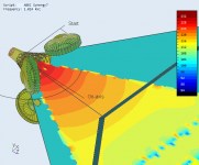
And at 1000Hz, just before the drop:

You can see how it peaks slightly above 1kHz, and that -3dB from the flat section is around 1.5kHz. The peak is rounder thanks to Kessito´s tip on using damping to get more realistic results - not assuming perfectly reflective surfaces, but allowing some absorbtion.
All four mids are now in the BEM part of the model, except the rear chambers, which are simulated as a simple enclosure in the LEM section.
Raw response of each driver 90-92dB efficiency (peak values) 1m from horn mouth compared to around 85db at 1m from driver (also peak values) in the bandpass alone.
Adding a LR2 filter @ 1300Hz:
Here´s the difference in amplitude response between the single bandpass driver and the same bandpass driver in the horn. The absolute levels is off, since it´s measured at different distances, but if we assume the top flat part is regular horn loading, I think can explain drop from ca 1150Hz as the reflection from the throat.
It appears to me that since the -3dB level of the bandpass driver by itself is around 1500Hz, it should be possible to get more extension by moving the mids even closer.
Naturally, moving the mids closer brings them more into the view of the compression driver, and the holes will be relatively bigger compared to the throat area there.
So the question is whether the response now is OK - can the DE250 cross over at this level in a domestic environment without strain? I should think so, but please correct me if i´m wrong.
I would tend to think that for maximum output, and less regard for fidelity, one would move the holes slightly closer to the compression driver, but for home use it´s best to leave them where they are. Any inputs?
PS: Only the mid chambers have had damping added to them. Next time I run the solver I will add some damping to the horn, QTWG etc.
Added:
Here´s field showing the frequency with maximum cancellation. You can see high SPLs near the compression driver but very low travelling towards the mouth.
And at 1000Hz, just before the drop:
Attachments
-
 2015-02-02 22_05_32-ABEC3 - ABEC Synergy7.png104.4 KB · Views: 701
 -
 2015-02-02 22_08_31-ABEC3 - ABEC Synergy7.png31.9 KB · Views: 702
 -
 2015-02-02 22_13_02-ABEC3 - ABEC Synergy midrange test.png99.3 KB · Views: 671
 -
![2015-02-02 22_14_08-VacsViewer - (new) - [SPL].png](/community/data/attachments/422/422116-033b5b32669470bb856f0336b80a026a.jpg?hash=AztbMmaUcL) 2015-02-02 22_14_08-VacsViewer - (new) - [SPL].png41 KB · Views: 694
2015-02-02 22_14_08-VacsViewer - (new) - [SPL].png41 KB · Views: 694 -
![2015-02-02 22_21_34-VacsViewer - (new) - [SPL].png](/community/data/attachments/422/422127-930fa9cb72887b5344c447b3cb099b89.jpg?hash=kw-py3KIe1) 2015-02-02 22_21_34-VacsViewer - (new) - [SPL].png47.7 KB · Views: 661
2015-02-02 22_21_34-VacsViewer - (new) - [SPL].png47.7 KB · Views: 661 -
![2015-02-02 22_24_04-VacsViewer - (new) - [SPL].png](/community/data/attachments/422/422140-2761ae6e039232f38bf8c850aae802d2.jpg?hash=J2GubgOSMv) 2015-02-02 22_24_04-VacsViewer - (new) - [SPL].png46 KB · Views: 689
2015-02-02 22_24_04-VacsViewer - (new) - [SPL].png46 KB · Views: 689 -
![2015-02-02 22_30_27-VacsViewer - (new) - [SPL - Copy].png](/community/data/attachments/422/422152-041b89b05d72e91ba10a6c6cf43a84ac.jpg?hash=BBuJsF1y6R) 2015-02-02 22_30_27-VacsViewer - (new) - [SPL - Copy].png37.1 KB · Views: 664
2015-02-02 22_30_27-VacsViewer - (new) - [SPL - Copy].png37.1 KB · Views: 664 -
 2015-02-02 22_45_57-ABEC3 - ABEC Synergy7.png82.5 KB · Views: 668
 -
 2015-02-02 22_48_03-ABEC3 - ABEC Synergy7.png77.6 KB · Views: 695
Last edited:
Geddes crosses DE250 over at 900 hz in Summa, I believe
I doubt it will have any strain at all up at 1200 or 1300 hz.
You might need LR4 on the CD to match the slope of the mid and then there should be little doubt re' strain
I doubt it will have any strain at all up at 1200 or 1300 hz.
You might need LR4 on the CD to match the slope of the mid and then there should be little doubt re' strain
Last edited:
nc535: Thanks.
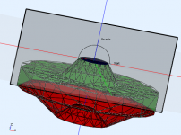
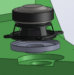
A simpler way perhaps, as suggested by several here, but that I have discussed with Fluid over the last couple of days. Thought I would display it here. Work in progress, but thought this might be simpler to print. Simply route away two simple holes, stick the adapter inwith the driver fixed already.
Its easy to get stuck with an idea -- one of the nice things about this forum is the direct but friendly criticism and support. 🙂

Several adapter depths and frustums/openings could be printed for a low price. Simply use the one that gives the response you like. Of course, with this variant you have to choose an entry point, but looking at the response curves, it seems like the midrange driver has some overlap, so I doubt this entry point will fail to overlap with the compression driver.

I do think Patrick is correct that a phase plug won´t do much in this case, but I don´t think the reason is what he states (sorry Patrick - please correct me if I´m misinterpreting this - i´m eager to learn).
I think the reason in this case is that the midrange drivers in a bandpass already has sufficient bandwidth so that the limiting factor becomes the reflection frequency. If the midrange had been bigger, so that the chamber would induce more cancellation, and the bandpass drop-off had been lower in frequency than the reflection frequency, a phase plug had been useful.
A simpler way perhaps, as suggested by several here, but that I have discussed with Fluid over the last couple of days. Thought I would display it here. Work in progress, but thought this might be simpler to print. Simply route away two simple holes, stick the adapter inwith the driver fixed already.
Its easy to get stuck with an idea -- one of the nice things about this forum is the direct but friendly criticism and support. 🙂
Several adapter depths and frustums/openings could be printed for a low price. Simply use the one that gives the response you like. Of course, with this variant you have to choose an entry point, but looking at the response curves, it seems like the midrange driver has some overlap, so I doubt this entry point will fail to overlap with the compression driver.
I do think Patrick is correct that a phase plug won´t do much in this case, but I don´t think the reason is what he states (sorry Patrick - please correct me if I´m misinterpreting this - i´m eager to learn).
I think the reason in this case is that the midrange drivers in a bandpass already has sufficient bandwidth so that the limiting factor becomes the reflection frequency. If the midrange had been bigger, so that the chamber would induce more cancellation, and the bandpass drop-off had been lower in frequency than the reflection frequency, a phase plug had been useful.
Attachments

Last edited:
The main thing controlling the bandwidth of the mids is the relative size of the port vs the volume of the driver chamber behind it. If you look at the Trynergy, it uses essentially 1/4 of your mids (a 3FE22 but 3FE25 would have similar) behind a 2inx2in throat to achieve bandwidth up to 20kHz. In a tractrix, the cone loading was so good I was getting 110dB sensitivity at 2.83v and cone motion was like 50 microns at 100dB. Try playing around with your hole diameter vs chamber volume ratio. The replaceable inserts is an excellent idea.
I've been going kinda nuts building Synergy horns since I bought a printer. (OK, I'm always nuts, but this month I'm really on a tear.)
The measurements and designs are mostly here:
250 - A Sweet Front Stage On The Cheap. - Page 2 - Car Audio | DiyMobileAudio.com | Car Stereo Forum

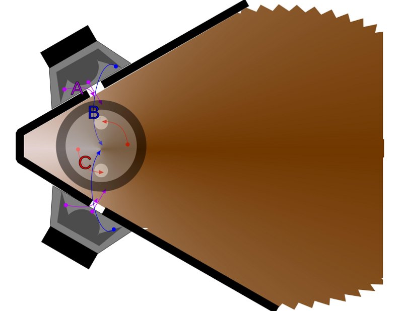
I think the M2 waveguide might offer a couple of advantages for a Synergy horn. First, the knuckles on the waveguide are designed to absorb higher order modes. JBL doesn't call them "HOMs", but that's what they're talking about. Those 'troughs' in the waveguide absorb reflections from the mouth. It's similar in effect to covering the waveguide in felt, like Dunlavy Audio Labs did.
The other nice thing about the M2 waveguide is that we can 'tuck' the Synergy midranges into the 'knuckles'
Once you spend a few hours designing Synergy Horns in a 3D program, you start to see that the midrange taps take up a lot of space on the waveguide. In some of my designs, the depth of the midrange taps gets as deep as 1-2". That takes up a lot of space, increases the pathlength, etc. The 'knuckles' on the M2 give us some space to hide the midrange taps.

Geometrically, we make an M2 waveguide the same way that we make an Altec Tangerine Phase Plug. We take 'slices' out of the shape using a wedge. (The wedge defines the expansion rate of the phase plug.)


Here's a pic of the design coming together. It's not perfect but you get the general idea of how to make it.
Another thing I like about the M2 waveguide is that it's an evolution of a waveguide profile that's already proven to work well. If you look at the side walls of the M2, it might appear that they're flat. But with a closer look, you'll notice they're gently curved.

The JBL M2 waveguide is basically a JBL progressive transition waveguide with an Altec Tangerine phase plug 'pressed' into the shape.
The measurements and designs are mostly here:
250 - A Sweet Front Stage On The Cheap. - Page 2 - Car Audio | DiyMobileAudio.com | Car Stereo Forum
I think the M2 waveguide might offer a couple of advantages for a Synergy horn. First, the knuckles on the waveguide are designed to absorb higher order modes. JBL doesn't call them "HOMs", but that's what they're talking about. Those 'troughs' in the waveguide absorb reflections from the mouth. It's similar in effect to covering the waveguide in felt, like Dunlavy Audio Labs did.
The other nice thing about the M2 waveguide is that we can 'tuck' the Synergy midranges into the 'knuckles'
Once you spend a few hours designing Synergy Horns in a 3D program, you start to see that the midrange taps take up a lot of space on the waveguide. In some of my designs, the depth of the midrange taps gets as deep as 1-2". That takes up a lot of space, increases the pathlength, etc. The 'knuckles' on the M2 give us some space to hide the midrange taps.
Geometrically, we make an M2 waveguide the same way that we make an Altec Tangerine Phase Plug. We take 'slices' out of the shape using a wedge. (The wedge defines the expansion rate of the phase plug.)
Here's a pic of the design coming together. It's not perfect but you get the general idea of how to make it.
Another thing I like about the M2 waveguide is that it's an evolution of a waveguide profile that's already proven to work well. If you look at the side walls of the M2, it might appear that they're flat. But with a closer look, you'll notice they're gently curved.
The JBL M2 waveguide is basically a JBL progressive transition waveguide with an Altec Tangerine phase plug 'pressed' into the shape.
Last edited:
Patrick,(OK, I'm always nuts, but this month I'm really on a tear.)
I think the M2 waveguide might offer a couple of advantages for a Synergy horn. First, the knuckles on the waveguide are designed to absorb higher order modes.
The JBL M2 waveguide is basically a JBL progressive transition waveguide with an Altec Tangerine phase plug 'pressed' into the shape.
The "Tangerine" phase plug was easier to injection mold in plastic than the usual circumferential slit phase plugs, but other than the difference in materials, did not do much of anything different than the circumferential slit still used in most compression driver designs.
What makes you think a reflective "knuckle" would "absorb higher order modes" ?
Art
Patrick,
The "Tangerine" phase plug was easier to injection mold in plastic than the usual circumferential slit phase plugs, but other than the difference in materials, did not do much of anything different than the circumferential slit still used in most compression driver designs.
What makes you think a reflective "knuckle" would "absorb higher order modes" ?
Art
There's a podcast linked on avs forum that describes what the knuckles are there for better than I can. The podcast is with the designer of the waveguide. In a nutshell, he acknowledges that there is a 'diffraction device' in the waveguide.

The designer of the waveguide talks about how a traditional diffraction slot creates diffraction at a single point in time. (The point where the wavefront diffracts over the edge.)
The M2 waveguide also has a slot, but the transition happens across the entire surface of the waveguide, spreading the diffraction out in time and intensity. The designer specifically attributes the smooth frequency response and says it sounds "like a silk dome" because of the waveguide innovations.
It's an interesting interview, because a lot of the issues he discusses seem to be pulled from both the Geddes playbook, as well as JBL's own research. The design draws liberally from a lot of other designs.
It's definitely worth a listen.
I agree, this month you are "really on a tear" a "diffraction device" causes, rather than absorbs HOMs.There's a podcast linked on avs forum that describes what the knuckles are there for better than I can. The podcast is with the designer of the waveguide. In a nutshell, he acknowledges that there is a 'diffraction device' in the waveguide.
Get back on the meds ;^).
As I recall the podcast and the paper, the knuckles increase the dispersion at HF, to overcome beaming above the throat size limit. The claim was made though that it was a sonic improvement, despite the diffraction and possibility of HOMs. First you need to test their result with your own ears. If you seek to duplicate those results, be prepared for some iterations. Why try? You should be able to get adequate dispersion with a 1" throat without the knuckles. Yes, you could hide mid ports down in there but I don't think mid holes are what are limiting performance of Synergy horns without knuckles.
I agree, this month you are "really on a tear" a "diffraction device" causes, rather than absorbs HOMs.
Get back on the meds ;^).
If you want to see some diffraction measurements, read this: Car Audio | DiyMobileAudio.com | Car Stereo Forum - View Single Post - 250 - A Sweet Front Stage On The Cheap.
As I recall the podcast and the paper, the knuckles increase the dispersion at HF, to overcome beaming above the throat size limit. The claim was made though that it was a sonic improvement, despite the diffraction and possibility of HOMs. First you need to test their result with your own ears. If you seek to duplicate those results, be prepared for some iterations. Why try? You should be able to get adequate dispersion with a 1" throat without the knuckles. Yes, you could hide mid ports down in there but I don't think mid holes are what are limiting performance of Synergy horns without knuckles.
An externally hosted image should be here but it was not working when we last tested it.
In a traditional constant directivity horn, the horn 'necks' down in one axis.
The reason that it 'necks' down is to control directivity to a higher frequency.
For instance, if you have a compression driver with a 1.5" exit, like the JBL D2360a in the JBL M2, the exit of the compression driver dictates that directivity is controlled to 9khz.
speed of sound / 1.5" =
13,500 / 1.5" =
9000hz
So necking it down to 1" increases high frequency directivity control to 13,500hz.
So far, so good right?
The problem is that when the horn 'necks down', it reflects energy back into the diaphragm. IE, higher order modes.
An externally hosted image should be here but it was not working when we last tested it.
M2 has that diffraction slot, just like the old school horns do. But the slot is 'spread out' across the surface of the waveguide.
- Status
- Not open for further replies.
- Home
- Loudspeakers
- Multi-Way
- Synergy horn - 3d printing entry?