Most of the 1.4" and 1.5" compression drivers that I've seen are simply the same motors that the manufacturer uses for their 1" model, but with a different exit size.
If anything, I'd actually like to get compression drivers with a 3/4" or even a 1/2" exit.
I know B&C offers some, I should probably order a couple and see what I can come up with, as far as waveguides go. I'd avoided those models in the past because the selection of 3/4" waveguides is slim pickings.
I'm not entirely sure why, but the M2 style waveguide seems to have more extended high frequency response. Measurements are here:
Car Audio | DiyMobileAudio.com | Car Stereo Forum - View Single Post - 250 - A Sweet Front Stage On The Cheap.
Patrick,
I disagree with the difficulty mating to wood. First, I would do the expansion just outside the pole piece. Since this would be a CD waveguide it would have a much wider coverage angle than the EAW shown. That would also make the throat section more shallow than the EAW, able to fit in cone. Use the M2 for example, the waveguide is pretty shallow. The would terminate to a rectangle with something like 45 degrees & 30 degrees. Then you would build a rectangular conical expansion horn with a rectangular entrance with 45 x 30 deg walls.
I disagree with the difficulty mating to wood. First, I would do the expansion just outside the pole piece. Since this would be a CD waveguide it would have a much wider coverage angle than the EAW shown. That would also make the throat section more shallow than the EAW, able to fit in cone. Use the M2 for example, the waveguide is pretty shallow. The would terminate to a rectangle with something like 45 degrees & 30 degrees. Then you would build a rectangular conical expansion horn with a rectangular entrance with 45 x 30 deg walls.
Latest status:
I have discovered a bug in ABEC3, specifically that the Baffle element in the software does not accept a WallImpedance parameter. The author will fix it, hopefully by end of february. For now, I will assume that moving the entry holes slighly offset from center won´t remove too much upper bandwidth. Currently, the midranges reach higher than they need to, because the reflection frequency kicks in before midranges run out of extension. I will sim this once I get the software update.
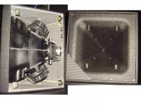
For now, I´m focusing on making this buildable. It seems to me that moving to a two mids per side has great benefits in making it possible to construct. So here is the latest iteration:
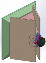
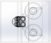
I started explaining it in writing, but I suppose the pictures explain it, or at least I hope. One thing I can mention is that the adapter is divided in two bits - the red one and the purple one. The red one makes it possible to attach the CD to the rest of the adapter.


I have discovered a bug in ABEC3, specifically that the Baffle element in the software does not accept a WallImpedance parameter. The author will fix it, hopefully by end of february. For now, I will assume that moving the entry holes slighly offset from center won´t remove too much upper bandwidth. Currently, the midranges reach higher than they need to, because the reflection frequency kicks in before midranges run out of extension. I will sim this once I get the software update.
For now, I´m focusing on making this buildable. It seems to me that moving to a two mids per side has great benefits in making it possible to construct. So here is the latest iteration:
I started explaining it in writing, but I suppose the pictures explain it, or at least I hope. One thing I can mention is that the adapter is divided in two bits - the red one and the purple one. The red one makes it possible to attach the CD to the rest of the adapter.
Attachments


More likely it would look like a Danley SM60-f.
Start with a B&C coax with a removable waveguide and it should be easier to mate to a new printed conical waveguide and woofer chamber.
http://www.danleysoundlabs.com/danley/wp-content/uploads/2012/04/SM-60F-spec-sheet1.pdf
So that is really interesting to take a 5in coaxial and feed the cone into 4 little mid injection ports and the center CD coax through the vertex inlet. Then take the woofer and use re-entrant reflex into horn.
Yes, that is the standard Danley configuration, conical all the way. Why not try something a little different in the expansion area? The holes have to create diffraction, so why not use a design like the M2 that makes use of the diffraction to potentially widen the usable coverage and smooth the high end.
This is really a fun, cutting edge project. Do you want to borrow a couple of unused 3FE25`s? I find it very motivating to have some of the hardware at hand when sketching on a project.
Wouldnt a BMS 4550 give you more overlap to work with as it is capable to sound good crossed over from >800Hz? Danley has recommended using the BMS drivers for Unity-horns on several occasions. Curves
Wouldnt a BMS 4550 give you more overlap to work with as it is capable to sound good crossed over from >800Hz? Danley has recommended using the BMS drivers for Unity-horns on several occasions. Curves
I really hope that this design will be based on bms 4550 and 3fe25.
Because that is what i own..
The only thing i plan to do different is 60x40 degree horn.
Because that is what i own..
The only thing i plan to do different is 60x40 degree horn.
Naturlyd: Thanks, and thank you for the offer. I might take you up on this. At some stage I need to measure the drivers with the printed adapters and see how they match with ABEC.
To be honest, for the compression driver question, it´s really a question of 1) laziness - I know the DE250 is used in many SEOS projects and Geddes uses it, but mostly 2) lack of knowledge on how to model a compression driver in ABEC.
For the CD I have been thinking like this: any decent CD will give plenty of SPL for home use, so the shape of the response is less important - the important thing to get right is the distance to the diaphragm, so that the positioning of the midrange gets correct.
However, I might be overthinking it, as a slight miss can be corrected by the crossover - unless the mids are can´t reach high enough that is.
So, you are in Norway? Are you going to overthink this until it gets warm enough there for outdoor measurements?🙂
I think you are ready to print. The only thing I don't see in your last drawing is where you are going to put the woofers. You'd have more room for them on the horizontal flares, but you would have to cut down the front portion of the vertical sides and extend the horizontal sides. This does make cutting the wood a little trickier...
The 3Fe25's that I ordered Sunday are supposed to be delivered today. (I'm a lot closer than you.) I also have a pair of 4Fe35's on hand that I'll be testing. I was struck by how similar these drivers are. In hornresp, the top end of their FR is exactly the same but the 4FE can extend down a bit lower and can safely do almost 10 db more maximum SPL by virtue of its larger Sd, Xmax, and power handling. If one has space for it, the bigger one seems a better choice.
I will be using mailing tube to make a chamber for the 3FE25 and a 3" PVC pipe cap and coupling, which have ID of 3.5", to make a chamber for the 4FE35. If you send me the STL files for the 3FE cap and insert, I would get one printed and test it for you. I know there is a 3D printer in my future but I haven't bought one yet...and I want to ease in gently.
You might ask why I am giving up on the 8" driver approach if you've seen or recall my posts to that effect. I celebrated prematurely when I got good enough response with a phase plug in a test box. When I tried a couple of different ways to squeeze it into the tight confines of my corner horn package, I couldn't get enough damping in the chamber to suppress resonances or reflections off the walls (whatever they were), which were inband because of the size of the driver. I think I can still do a 2-way with the smaller drivers just by crossing over my base bin a little higher. On reflection (no pun intended), that will give me better control of the vertical polars and do better at suppressing floor and ceiling bounce nulls.
So good luck with your design. Don't keep us in suspense - print it!!!
Jack
Yeah. Gotta be careful measuring outdoor in Norway this time of the year.

Nice project Cookiemonster!
Nice project Cookiemonster!
Last edited:
Thanks for the feedback guys. I have not disappeared - was actually writing a response to you guys yesterday when my mac ran out of disk space, and Parallels crashed with no warning. So I'll respond when I have time to sit down again.
Nice picture Omholt - is that you?
Nice picture Omholt - is that you?
BMS 4550 vs DE250
I have been discussing some thoughts with cookiemonster and considered the BMS4550 as an alternative. The issue with it is that it is physically different inside and this raises some questions.
It has an effective path length of 67mm which is longer than the driver itself. This is probably due to the fact that it has the diaphragm in a ring around the outside rather than the normal disc shape.
Here is a link to Paul Spencer's blog where there is a picture of a 4550 taken apart
Red Spade Audio: BMS 4550 compression driver
It is difficult to use Akabak to import into ABEC and there is no ready made ABEC model to use. If anyone can offer any information on how to model the BMS4550 in comparison to the DE250 to get a simulation of how it would affect the rest of the model then it could be used as an alternative.
If not then I think cookiemonster will stick with the DE250 as a known quantity.
Its easy enough to simulate how that extra length affects the response of the mids, at least to a first order. In HornResp, after you model the horn using the Sx and L12 values (e.g. from Bill Waslo's spreadsheet), increase L12 by the thickness of your CD mounting plate plus the acoustic path length of the CD. You can do a more detailed and accurate model in Akabak or ABEC but you can see the affect of the acoustic path length in HR by switching between two models that differ only in that L12 parameter.
The obvious effect is that the null due to the reflection from the CD's diaphragm occurs at a lower frequency, forcing a lower crossover point and/or steeper crossover slopes. I can't find the post where TD recommended the 4550. If I recall correctly, its phase plug is itself conical resulting in it producing a spherical wavefront at the exit of the CD and a good match to a conical horn. The benefits of this are in the HF, you may see less beaming there. This is not something that would show up in an ordinary simulation. CM's simulation is beyond ordinary but not that far beyond. Else you wouldn't have asked the question you asked.
I've got both BMS4550s and DE250 clones here and I'm trying both, aiming for a 950 Hz crossover in a wide 90x45 horn. The DNA-360 (clone) seems to have slightly better low end response than the 4550. Both seem workable choices. I could crossover higher with the DNA-360 but to do so would violate the Synergy rule regarding the relationship of the wavelength at crossover and the horn cross-section dimensions at the mid entry point. Thus to adapt to the 4550, I start by dialing in a steeper DSP high pass on the CD to match with the steep acoustic low pass on the mids caused by the longer CD path length of the 4550.
Its too early for me to choose between drivers via a listening test as my implementation so far has some other problems, hopefully solved by a switch to smaller mid drivers. I don't think this is a question that can be answered by simulation.
Jack
It's interesting to see why the BMS has longer path lengths: that the sound waves are forced backwards (towards the magnet) and then into a central exit. I have to admit I struggled with where the extra path length came from.
Yes nc535 - so far this sim only scratches the surface of what ABEC can do. I was hoping that the thread could stir up some interest, so we could get a little ABEC-community here on diyaudio, build up a library of scripts etc. 🙂 I am sure that ABEC is able to simulate to great detail these drivers, but that's clearly beyond my skill level now and probably forever.
However, for my purposes, I don't think it's necessary - the interesting bit is to capture 1) the reflection frequency, and 2) the influence the midrange ports has on the response of the sound exiting the CD.
On the second point, I think ABEC is superior to Akabak and Hornresp, because it will capture the effect of sound pressure being lower in the corners than on the sides of the horn. However, as Kessito pointed out, assuming 100% rigid surfaces will tend to exaggerate things, and this again points to Garbage in = Garbage out. There may be lots of garbage in the scripts.. 🙂
I can share the scripts here - you can easily modify to 90x45, except you need to model your own throat transition mesh and import it. Then you can replace the drivers, the entry points etc, and compare your Akabak/Hornresp if you'd like.
CM:
You are the pioneer in ABEC in this community and we all seem to be waiting for you to make further progress so that we can stand on your shoulders, which is how a lot of the progress is made in high tech. I want to have a Synergy horn before I struggle up the learning curve on ABEC. Its just so tedious to put in all those details in a model, be it a mechanical/CAD model or an acoustic or electrical model. If we could share, we could all move so much quicker. That is what open source communities are all about.
Right now though it seems quicker/easier to simulate enough to get in the ball park and then take off one's theoretician's hat and put on an experimentalist's hat. I actually enjoy my time in the lab and shop but I often find it frustrating as my mindset and hands are better suited to sitting in front of a computer.
I would love a copy of your ABEC script to learn from and then model what I've built and compare simulation to measurement and then adjust the model to minimize the difference.
I've got modeling that throat transition (in Sketchup) on my to do list already so why not ABEC as well? I think the throat transition will be my next stumbling block after I master construction of non-resonant mid chambers. What I have now is pretty crude...
Jack
nc535: I sent you a PM with a download link. I will post all the scripts here, but they do need some cleaning up to make them readable. Lots of weird variable names etc.
Fluid has shown that within the limitations (600x600x480) size, 10 inchers will be too big. Actually, it´s not that bad, because if one wants ports in the corners, it´s necessary with four drivers. Four eights should do the job nicely.
So now the question is: What kind of 8-inchers have low fs and works well playing into a compression chamber? Guess it´s time to experiment. The bandwidth will be quite limited, and hopefully it´s going to be possible to limit it acoustically, to get increased efficiency in a smaller passband. The Faitals go quite deep (at least in the sim), so I suppose 250 or 300Hz is a good crossover frequency.
- Status
- Not open for further replies.
- Home
- Loudspeakers
- Multi-Way
- Synergy horn - 3d printing entry?