If you are going 8", I would say take a look at the 8FE200s I started out with. Four of them will have no trouble getting down to 80 Hz vented, if you have enough box volume. And they will go up to at least 700 Hz without a phase plug for lots of overlap. They are about $50 ea.
Lots of choices depending on how low you want to go and what you already own or can find a deal on.
Lots of choices depending on how low you want to go and what you already own or can find a deal on.
Hornresp Compression driers
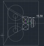
@nc535 Thanks for the information on the compression drivers. I had seen a similar basic idea suggested before. In order to try and get it right perhaps you can help me. I have attached a couple of shots of a 2D CAD drawing of the horn that CM is working on.
The overall shot is with 2 x 8" drivers on the side for comparison. The zoomed in section shows the CD and mid. The red line is 0.707" from the synergy spreadsheet. The blue line is the front of the CD at 1". The green line is the end of the Throat adapter as CM has designed it. The purple is 80mm from the red and the yellow line 96mm from the blue line.
To simulate this properly which are the best dimensions to use in the spreadsheet and how much extra L12 do you think I need to add?
I have tried adding an extra 6.7cm to L12 to simulate the extra path length, this does make the notch quite low in frequency. Should I be adding extra to simulate the DE250 as well?
Do you have any measurements of the two CD's you have to compare to a sim?
Attachments

I have simulations of the CDs alone that show both would be usable at least down to 900 Hz, as is already confirmed. Today I hope to get my 3FEs on the horn and measure them. Prior sims used larger mids had problems that got in the way of determining an L12 offset to correlate with HornResp. The failure though was in the accuracy of modeling of Vtc, Ap1, Lpt and my crude phase plug. The reflection null was fairly close to predicted or perhaps it was simply the least of my problems.
Where you add 6.7 cm for the BMS4550, I believe you should use 3 cm for the DE250. I've been using 3 cm for the DNA360 also but that is simply an assumption it matches the DE250. I've got an AkaBak model for the DE250 that I found in one of these threads and it includes a 3 cm "duct". My guess is a first pass approximation to a MBS4550 model would be to change that duct to 6.7 cm. Yes, when you use the BMS4550, the reflection null moves significantly lower. For some reason though, Tom Danley recommends its use nonetheless. The resulting steeper acoustic slope for the sub 1Khz mid crossover might actually be a good thing.
Where you add 6.7 cm for the BMS4550, I believe you should use 3 cm for the DE250. I've been using 3 cm for the DNA360 also but that is simply an assumption it matches the DE250. I've got an AkaBak model for the DE250 that I found in one of these threads and it includes a 3 cm "duct". My guess is a first pass approximation to a MBS4550 model would be to change that duct to 6.7 cm. Yes, when you use the BMS4550, the reflection null moves significantly lower. For some reason though, Tom Danley recommends its use nonetheless. The resulting steeper acoustic slope for the sub 1Khz mid crossover might actually be a good thing.
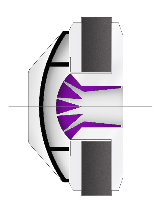
I think a good way to sim these things would be to forget about the motor etc of the compression driver, and only sim the actual response of the midranges downwards. However, the compression driver must be included to get a decent estimate of the reflection null. One way is to measure it and add that measure as a "duct", or another way is to draw the geometry, ending at the inverted dome.
I think I have a cross-section of a DE250 somewhere. It will be easy enough to draw some lines to see if the numbers match those mentioned in other threads. In ABEC, I want to include a number of small ducts though, to avoid any resonances that mask the effect we´re looking for.
I think I have a cross-section of a DE250 somewhere. It will be easy enough to draw some lines to see if the numbers match those mentioned in other threads. In ABEC, I want to include a number of small ducts though, to avoid any resonances that mask the effect we´re looking for.
So, looking at the cross-section red spade audio has posted, it appears that the DE250 has a conical section, about 27mm deep, starting at 1" and ending at 20mm diameter. Beyond this is the phase plug. It looks like the distance through the phase plug to the cone is about 15mm.
Total path length is therefore 27+15 = 42mm. Does this make sense?
So I include this on the BEM side of the model like this:
Shell "CD stub"; Subdomain=1; RefNodes="CD"; Position=100,101,102; Shelltype=Cone
HasBaffle=No; dD1=-20mm; dD=1in; tD1=27mm
On the LEM side, I need to add the 15mm to the diaphragm.
I figured I could make a simple phase plug by making ten conical sections like this. The diaphragm size is an estimation based on the same cross-section.
1780.000 mm2 area diapgragm total
178.000 mm2 one tenth of area diaphragm
7.527 mm diameter each tenth
314.159 mm2 area end of phase plug total
31.416 mm2 one tenth of end of phase plug
3.162 mm diameter each tenth
Waveguide "Phaseplug1" Node=61=62 dTh=7.572mm dMo=3.162mm Len=15mm Conical
Waveguide "Phaseplug2" Node=61=62 dTh=7.572mm dMo=3.162mm Len=15mm Conical
Waveguide "Phaseplug3" Node=61=62 dTh=7.572mm dMo=3.162mm Len=15mm Conical
Waveguide "Phaseplug4" Node=61=62 dTh=7.572mm dMo=3.162mm Len=15mm Conical
Waveguide "Phaseplug5" Node=61=62 dTh=7.572mm dMo=3.162mm Len=15mm Conical
Waveguide "Phaseplug6" Node=61=62 dTh=7.572mm dMo=3.162mm Len=15mm Conical
Waveguide "Phaseplug7" Node=61=62 dTh=7.572mm dMo=3.162mm Len=15mm Conical
Waveguide "Phaseplug8" Node=61=62 dTh=7.572mm dMo=3.162mm Len=15mm Conical
Waveguide "Phaseplug9" Node=61=62 dTh=7.572mm dMo=3.162mm Len=15mm Conical
Waveguide "Phaseplug10" Node=61=62 dTh=7.572mm dMo=3.162mm Len=15mm Conical
I don´t know if this will work, I need to resolve the model first, but does the logic seem reasonable?
Last edited:
Since there have been some requests, I changed my mind about the need to clean up the models before sharing. Here´s today´s snapshot.
One immediate improvement area is to make it more parametric, and make it easier to change variables. Now, some variables are entered several times, and especially those related to positioning are not done with "best practice" in mind, just "lets see how this works". 🙂 But as I mentioned, I will clean it up one day.
One immediate improvement area is to make it more parametric, and make it easier to change variables. Now, some variables are entered several times, and especially those related to positioning are not done with "best practice" in mind, just "lets see how this works". 🙂 But as I mentioned, I will clean it up one day.
Attachments
In your 3FE25 sims, what chamber volume and port hole diameter are you using? I'm just about to cut the mailing tubes.... It seems like for a Xover of 300 Hz or higher, it should be as small as possible, looking just at excursion but more volume flattens the hump below 400 Hz. I'm simulating 1.5L total for 4 drivers, net after removing driver displacement, because the resulting tube length just fits my box.
Last edited:
10mm chamber with diameter 73 (10 mm including the gasket up to the start of the cone), then a frustum with diameters 30 and 15mm, 10mm deep.
Rear volume needs to be tiny, i have set the sim to 0.2 liters per driver, bigger volumes will give a less dramatic roll-off on the bottom end.
The chamber is slightly smaller in the sim now, since I needed to reduce the diameter to make the circles fit in the BEM model. Once I can have damping on an offset hole Baffle element in ABEC, that´s not necessary anymore.
10mm chamber with diameter 73 (10 mm including the gasket up to the start of the cone), then a frustum with diameters 30 and 15mm, 10mm deep.
Rear volume needs to be tiny, i have set the sim to 0.2 liters per driver, bigger volumes will give a less dramatic roll-off on the bottom end.
The chamber is slightly smaller in the sim now, since I needed to reduce the diameter to make the circles fit in the BEM model. Once I can have damping on an offset hole Baffle element in ABEC, that´s not necessary anymore.
I hear you. .2L is even tinier than I was thinking for the low side but I only have a crude HR sim and a crude wooden horn
I'm going to start on the high side and then trim back depending on how I like what I see at the high end. I don't have a tapered frustrum, just a 12 mm thick horn wall. At some point I will thin that down to 3 mm around the mid port with a large forstner bit
In my sims, the rear chamber mostly affects the low-end response. How do you see it impacting your high-end response?

I had already decided to go with the small volume when you challenged me. If I do a sim in which the only thing that changes is the rear chamber volume, then the very high end is unaffected. What changes is the shape of the curve down from the peak at the low end to where the sharp rolloff begins at the high end. That isn't really a change in the high end so much as a flattening of the pass band but one that isn't really valuable. When I used the filter wizard in HR to flatten the low end peak for the low volume case, it flattened out the entire passband.
Is there a point in trying to make the acoustic roll-off as close to a 2. order LR as possible for example? So when you add an electrical 2nd order LR, you have your fourth order total roll-off, and an easier job when mating the woofers to it? It seems to me that for the woofers, one can forget about any real effect from the reflection, as the horn is too small, so here it´s only an electrical filter..
I think re' the slope is that there is no magic about any particular slope; what matters is the end result. In theory acoustical filtering is more beneficial than electrical. But with DSP and sufficient creativity, you should be able to make any slope work. What to slope to aim for at this stage in the game is beyond me. I just look for a shape that has reasonably flat phase around crossover. I would have to be confident of correlation between simulation and measurement to invest more time in it.
It won't be anything like a challenge to mount the woofers such that the reflection null won't hinder their ability to reach up to where they are crossed to the mids. The woofer reflection null will affect how much overlap you can have between woofers and mids and thus how steep a crossover you will need.
This becomes an issue if you want a passive crossover between the woofers and mids to save amp and DSP channels. Then you would push the woofers closer to the mids and try to make a 2nd order crossover work. You don't want to go too close because then the woofer holes may affect the response. Fortunately, with the mesh/BEM simulation you can quantify that.
So I had a go with the smaller 8 inch Faital driver. Seems to be a better fit altogether from what I can tell.
Didn´t spend any time trying to optimize crossover points etc now, just wanted to get a rough test. Even with four of these in each, the speaker won´t manage any dinosaur footprints.. 🙂 However, with some EQ it seems like they could integrate well with subwoofers now. The four woofers have 50 liters back chambers, which shouldn´t be too far off with the box size used.
In this simulation run, the diaphragm of the CD is held "dead", and the CD and Mid systems are run as one, ensuring coupling. The reflection null seen therefore includes the entire path to the diaphragm, as I mentioned in the previous post.

Again: These are peak values I believe. So subtract some (3dB?) for RMS.
Didn´t spend any time trying to optimize crossover points etc now, just wanted to get a rough test. Even with four of these in each, the speaker won´t manage any dinosaur footprints.. 🙂 However, with some EQ it seems like they could integrate well with subwoofers now. The four woofers have 50 liters back chambers, which shouldn´t be too far off with the box size used.
In this simulation run, the diaphragm of the CD is held "dead", and the CD and Mid systems are run as one, ensuring coupling. The reflection null seen therefore includes the entire path to the diaphragm, as I mentioned in the previous post.
Again: These are peak values I believe. So subtract some (3dB?) for RMS.
Attachments
![2015-02-16 00_19_12-VacsViewer - (new) - [SPL].png](/community/data/attachments/422/422338-c838cff08832a77c994a842c228882dc.jpg?hash=yDjP8Igyp3)
Last edited:
nc535 could you post a shot of the input parameters page for the Hornresp sim in post #251 it would be helpful to see what values you have used.
nc535 could you post a shot of the input parameters page for the Hornresp sim in post #251 it would be helpful to see what values you have used.
here you go
Attachments
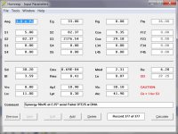
Thanks for image.
I have a few questions about the parameters you have used so I can try and understand this better as I have limited Hornresp experience. As you have 4 drivers in the model I have read that Vrc, Ap1, Vtc and Atc should 4 times the size of a single driver.
That makes your ports 18mm diameter by 3mm long.
Front chamber volume 7.5cc and area of 36.5mm diameter.
Rear chamber 0.2 litres.
I have used roughly the diameter of the driver as Atc and 30cc or more front volume as the air under the cone. Are you planning on using a big phase plug or have I got this wrong?
Lrc is 11cm this would make the rear chamber a very long thin tube. Is this right?
I thought 1.0 Pi space was a for a corner horn that went from floor to ceiling?
I am not trying to question your choices just trying to improve my understanding of the parameters people are choosing and why.
Thanks
re' " or have I got this wrong?"
You haven't got it wrong. I found that the response wasn't very sensitive to the value entered there by trying a range of values. If it had showed sensitivity, I would have measured by filling the cone with something and then pouring the contents into a measuring cup. Apparently I left the value down at the low end of the range that I tried. I'm sure the real value doesn't matter much. If there is a lesson there, its to always try a range of values for any parameter and then focus on those that seem to matter.
The definition of x pi space is independent of what the horn size. Would you change your definition if you were simulating a direct radiator placed in a corner? Its the walls that have to go all the way between floor and ceiling. That defines a corner. Its half as much space as an infinite baffle and therefore its 1 pi.
In any case, I only have 4 choices for the value in that box, which one would you have me pick?
I take the corner gain and boundary support with a grain of salt because how much gain you get depends on the construction of the corner, at least at low frequencies. I know I've got enough headroom in the design to make up the difference with EQ if I don't get as much gain as predicted. At 300 hz and up where I'm using this driver, even sheetrock should give good support.
@cookiemonster:
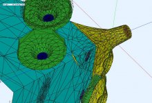
I had a look on your ABEC model and found out that there is an error in the QTWG Element in Subdomain 1. There is an small area which is not aligned correct. It is the small yellow area in the screenshot. The normal vector is pointing in wrong direction and thus the area is not correctly orientated. This will lead to an error in the simu.
Also the numbers of elemtens and DOFs is quite large, on my computer it would take 2-3hrs to solve the model. Symmetrie would be the way to go, but as I experienced ABEC has (or had?) its problems with symmetry and several (more than one) diaphs included.
For HF only simus I would highly recommend a quarter model, as the actual model has its practical limits to midrange only due to limiting computational time.
Best Regards
Andreas
Attachments
The main reason I have been trying to use Hornresp is so that I can help cookiemonster get a sanity check on the ABEC model by getting something similar out of hornresp for the same input. That way any changes can be tested in hornresp first to see how they work out before trying to change the ABEC model.
I am trying to compare apples to apples which is why I asked the questions about your parameters to make sure I hadn't got it all mixed up.
I have also found that some parameters make very little difference to the output in Hornresp. For me front chamber volume and port length seem to be related. As you increase front chamber volume the port length needs to be increased to keep the output the same.
The pi space is probably irrelevant as that is placement dependant. The reason I asked is that I had seen this question spoken about by David McBean.
Quote:
Originally Posted by oublie
Is a speaker flush mounted in a wall at listening height 1Xpi or 2Xpi radiation angle in other words do you still get the gain from the floor similar to the way hornresp models it or not?
Hi oublie,
There will be some enhancement of the SPL response when the dimensions of the radiator and the distance to the floor are small compared to the wavelength. For the arrangement you have described though, I think it would be best to assume worst-case conditions and set Ang = 2 x Pi in any Hornresp simulations.
Kind regards,
David
- Status
- Not open for further replies.
- Home
- Loudspeakers
- Multi-Way
- Synergy horn - 3d printing entry?