Dey look like butt cheeks rather than knuckles - but they do improve HF dispersion via diffraction in a smooth controlled way. Nothing to do with absorbing higher order modes.
Dey look like butt cheeks rather than knuckles - but they do improve HF dispersion via diffraction in a smooth controlled way. Nothing to do with absorbing higher order modes.
Higher order modes are sound waves that don't travel straight down a waveguide or horn
for instance, a wave that's reflected off of the mouth and back into the throat

The M2 waveguide is a two piece design. On the left are the butt cheeks. On the right are the knuckles.
Here in this pic we see a JBL loudspeaker with the buttcheeks, the Gedlee Summa that was inspired by it, and Geddes himself
The knuckles are a diffraction device. So is a diffraction slot. The difference between the knuckles diffraction device and a diffraction slot is that the knuckles spread the diffraction out over time.
In a nutshell, it's important to understand that the butt cheeks aren't the device generating the diffraction. It's the diffraction device or diffraction slot that's generating the diffraction.

One way to eliminate the diffraction is to eliminate the diffraction device, which is exactly what JBL did with the progressive transition waveguide.
That is a terrible example of a constant directivity horn. Are you setting up a paper tiger? There is a generation of CD horns that don't rely on diffraction, the SEOS family being an example.
What I find interesting is the M2 uses diffraction and apparently somehow escapes honk/HOMs. Or maybe they accept some in order to get better HF dispersion. I don't know; I haven't heard them.
What I find interesting is the M2 uses diffraction and apparently somehow escapes honk/HOMs. Or maybe they accept some in order to get better HF dispersion. I don't know; I haven't heard them.
That is a terrible example of a constant directivity horn. Are you setting up a paper tiger? There is a generation of CD horns that don't rely on diffraction, the SEOS family being an example.
What I find interesting is the M2 uses diffraction and apparently somehow escapes honk/HOMs. Or maybe they accept some in order to get better HF dispersion. I don't know; I haven't heard them.
As noted in the last post, you can eliminate the diffraction by eliminating the diffraction device.
But sometimes your design calls for a diffraction device.
In the project that I am currently working on, I literally cannot think of another way to do it, short of using a ribbon or a direct radiator. I can't get the coverage angle I need, in the space that I have, without a diffraction device.
I honestly sold my car because they weren't big enough for the SH50s
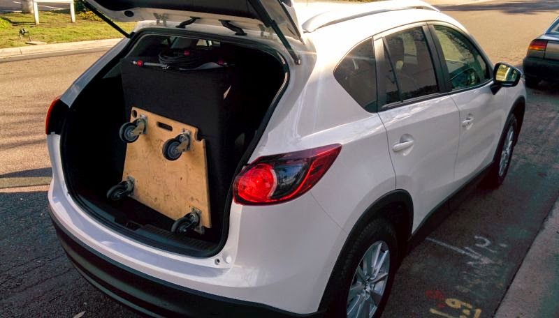
Basically bought the SUV version of it. (Sold a Mazda6, bought a CX-5)
The CX-5 is *just* big enough to hold two SH-50s
Basically bought the SUV version of it. (Sold a Mazda6, bought a CX-5)
The CX-5 is *just* big enough to hold two SH-50s
I don't get it where is the "X" shaped "knuckle" in the M2?
See that "X" on the right?

When you take the shape and press it into a conventional biradial horn, you get this:


For comparison's sake, here's JBLs:
An externally hosted image should be here but it was not working when we last tested it.
The JBL design is a little shallower than mine. If you want to replicate the JBL design, tweak my angles. I used 90 degree horizontal and 45 degree vertical.

See the slits in an Altec tangerine phase plug? It's the same process. Altec uses eleven slits, JBL uses four.

Here's Kefs
Last edited:
Patrick, I think that needs to be a topic in a new post as it kind of muddies the waters here. Let's focus on the synergy horn and optimizing it's design, rather then starting on a new design based of JBL's new waveguide.
Well, count me interested. These are the two designs, the SH50 and the M2, that I am most interested in hearing and have thought along the same lines as Bateman.
Bateman, what are your thoughts on the mid horn terminations, or rather where and how do you envision "hiding" the mids in the "knuckles"? hmmm, if SH50 and M2 mated...
Bateman, what are your thoughts on the mid horn terminations, or rather where and how do you envision "hiding" the mids in the "knuckles"? hmmm, if SH50 and M2 mated...
Well, count me interested. These are the two designs, the SH50 and the M2, that I am most interested in hearing and have thought along the same lines as Bateman.
Bateman, what are your thoughts on the mid horn terminations, or rather where and how do you envision "hiding" the mids in the "knuckles"? hmmm, if SH50 and M2 mated...
You can do some interesting things when you're no longer working with wood.
Stay tuned to the updates in my thread at Diyma
this is a natural and obvious idea for mids placemet 🙂 ..if SH50 and M2 mated...
Sure, if we had or could make M2-like waveguides with great SQ, then we could build synergies with 1.4" CDs with low enough mid to CD crossover frequencies that 2-way synergies that covered from subwoofer territory up would be much easier to do. That is indeed a worthy challenge.
Sure, if we had or could make M2-like waveguides with great SQ, then we could build synergies with 1.4" CDs with low enough mid to CD crossover frequencies that 2-way synergies that covered from subwoofer territory up would be much easier to do. That is indeed a worthy challenge.
Most of the 1.4" and 1.5" compression drivers that I've seen are simply the same motors that the manufacturer uses for their 1" model, but with a different exit size.
If anything, I'd actually like to get compression drivers with a 3/4" or even a 1/2" exit.
I know B&C offers some, I should probably order a couple and see what I can come up with, as far as waveguides go. I'd avoided those models in the past because the selection of 3/4" waveguides is slim pickings.
I've seen 1.75" or 2" diameter diaphragms in 1" exit CDs and that you can get 3" and 4" diameter diaphragms in the larger exit sizes. Even if the motor remains the same, the larger diaphragms result in lower extension.
Perhaps with B&C 1/2" exit, you can get that dispersion you are looking for w/o resorting to diffraction. You will definitely get a smaller package as the device doesn't need a lot of space behind the waveguide
Perhaps with B&C 1/2" exit, you can get that dispersion you are looking for w/o resorting to diffraction. You will definitely get a smaller package as the device doesn't need a lot of space behind the waveguide
Hi Patrick,
then perhaps you should have a look on those new 3/4" celestion drivers?
Compression Drivers / Neo - CDX07-1075 - Celestion - Guitar, Bass & Pro Audio Speakers
Grüße
Andreas
then perhaps you should have a look on those new 3/4" celestion drivers?
Compression Drivers / Neo - CDX07-1075 - Celestion - Guitar, Bass & Pro Audio Speakers
Grüße
Andreas
Patrick,
I like your idea of combining a M2 style horn throat with the entry holes for the synergy mids. I think this method will likely yield the smoothest combined HF response.
There is one type of synergy driver I believe would allow a the holes to be placed closer to the CD exit. This would also allow smaller and simpler implementation. This solution is actually buried in the Delaney patents. Instead of using multiple mids, why not use a small coaxial driver? The horn section in front of the cone would be the compression chamber and the entry hole can be place anywhere in the cone section. The horn entry would be mated to the center pole piece throat and the mid front gasket. this would be a pretty simple object to print, so you can experiment with different configurations without huge cost. in the end you would have a device that would bolt to a simple wood horn with a few screws. DIY soundgroup as a 6" Eminence coax that could be used for experimentation. If it worked out well maybe we could get some custom made with lighter cones and a narrower magnet gap/underhung voice coil.
I have done some digging an I have not seen anyone trying this method. If anyone has seen this done, please pipe up.
Patrick,
I like your idea of combining a M2 style horn throat with the entry holes for the synergy mids. I think this method will likely yield the smoothest combined HF response.
There is one type of synergy driver I believe would allow a the holes to be placed closer to the CD exit. This would also allow smaller and simpler implementation. This solution is actually buried in the Delaney patents. Instead of using multiple mids, why not use a small coaxial driver? The horn section in front of the cone would be the compression chamber and the entry hole can be place anywhere in the cone section. The horn entry would be mated to the center pole piece throat and the mid front gasket. this would be a pretty simple object to print, so you can experiment with different configurations without huge cost. in the end you would have a device that would bolt to a simple wood horn with a few screws. DIY soundgroup as a 6" Eminence coax that could be used for experimentation. If it worked out well maybe we could get some custom made with lighter cones and a narrower magnet gap/underhung voice coil.
I have done some digging an I have not seen anyone trying this method. If anyone has seen this done, please pipe up.
Yep, a coax will work.
It's virtually impossible to implement in wood.
This is because you have to mate the cone shape to the waveguide.
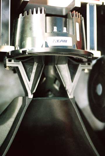
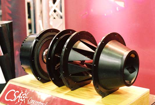
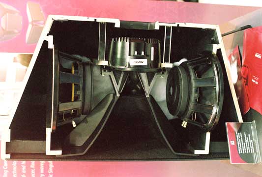
It might look something like this EAW loudspeaker.
Pics and article courtesy of aes042
- Status
- Not open for further replies.
- Home
- Loudspeakers
- Multi-Way
- Synergy horn - 3d printing entry?