@Nissep & JZatopa: Thanks for the input on the model, and tips on MeshMixer!
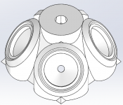
I have redone it again to improve printability. I see that it doesn´t fit on the MakerBot Replicator 2 still (is that the printer you have, Nissep?), but at least MeshMixer only needs to put support in the entry holes for the midranges.
There are no holes for mounting drivers now. Perhaps it´s best to just drill pilot holes and use self-tapping screws to fix things? Any experience with fasteners? For the CD I could include holes as those will be vertical, while it will be more tedious with the midranges, as those holes would need support I suppose.
Still no "mount to wooden horn" bits added though. I am thinking some kind of buckle, or perhaps long machine screws external to the wooden horn and adapter to attach it. Any ideas here?
STL file attached as zip file.
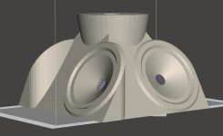
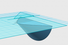
Attachments


I just took a look at the file and the overhangs aren't terrible, they could be printed with a reasonable amount of support. You could also add a few parts to make it print without support. I could print this on my printer but it going to be a very big and long print. Personally, I wouldn't want to invest in printing this unless you were 100% sure it was as good as possible.
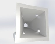
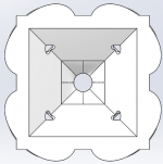
I am wondering if this design could be improved a bit more. The beauty of 3d printing is that curves are easy. A simple thing I see is that instead of the hard corners internal to the horn, you could add a fillet and smooth it out a bit. You could also put a radius on the midrange hole openings. A few others have mentioned that you could model a smooth transition, instead of the two step transition. I think this would be a worthwhile endeavor.
If you were the one doing the printing, this would be something you could do through an iterative design process. Since you don't have that as an option I would do everything you can to bring your design to perfection before printing it.
I would love to see a similar design based on an oblate spheroid waveguide that has no straight sides. I know that is outside the scope of this thread but it would be cool to see.
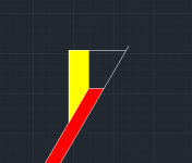
I put a radius on the opening now. 0.5mm. 🙂 I doubt it will mean anything acoustically. I think what you mean is getting a flared exit, which is probably a good thing. The thing is, I dont have any simple way to model the effect of that without running the whole exit through the BEM part of ABEC, which is going to take a long time both to get the mesh file in properly and also to simulate it. So I´m more comfortable with building something similar to what I´m simming at the moment.
What do you expect to be the benefit of an OS waveguide compared to the "square" variant? I´m sure I could google it - but just give a quick explanation. Several people on this forum refer to the corners as a good place to put the entries because aparently the sound pressure from the CD is lower there, so the holes interfere less with the output from the CD.
Anyway, if I can help in any way with your OS project just let me know. Unfortunately, I´m out of time and mental capacity, so I feel i need to complete this first before starting over. 🙂
Cookie:
As you've drawn it, there seems to be no alternative to a simple, permanent glued butt joint. If you could afford to make it a little bigger, then you could print a socket for the wood horn with walls of say 12 mm thickness to slide into and then lock it in place with a few screws through the plastic into the wood.
You definitely need CD mounting holes. I see you took them out; for printability reasons? If it can't be done as you first had then perhaps a small lip at the CD mounting surface around the entire perimeter of that surface. One would mount the CD to a thin CD mounting plate and then attach that plate to the lip. There would have to be a recess for the CD mounting holes... Of course the lip overhangs, which might be a problem but at least access to its underside isn't.
@nc535 Yes, the mounting holes - just took them out, as they are easier to put in when everything else is OK.
About fasteners.. I am reluctant to glue this alone, but your other idea is interesting.
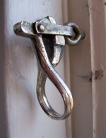
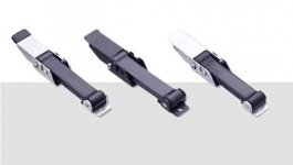
What I had in mind though, was something like this. Here´s where my vocabulary falls short, so I´ll just post the first example I found of a latch, even if there is a better example afterwards. 🙂 Old windows have these:

Diving canister lights typically attach their lids like this. So it gets really nice and tight, and there is just a thin compressible membrane between.
Perhaps somebody could help with what these are called?

I think the diving light type should work very well for the Synergy adapter. Tight, solid and reversible.
About fasteners.. I am reluctant to glue this alone, but your other idea is interesting.
What I had in mind though, was something like this. Here´s where my vocabulary falls short, so I´ll just post the first example I found of a latch, even if there is a better example afterwards. 🙂 Old windows have these:
Diving canister lights typically attach their lids like this. So it gets really nice and tight, and there is just a thin compressible membrane between.
Perhaps somebody could help with what these are called?
I think the diving light type should work very well for the Synergy adapter. Tight, solid and reversible.
Attachments
Yes! that will work. a plug/socket arrangement with a buckle to keep surfaces mated tightly
So how big a printer work space do you need for this? I thought I had found the mother lode with Solidoodle Workbench, which can print 12x12x12" for $1279, until I read reviews and saw their quality problems.
I'm starting to think this is the way to go except that it forces one into a 3 way design. Long term though, its just another set of drivers, amp, and DSP channel and it may well be that the low end extension of the 3way and the high end improvement of the 3D printed, quadratic throat are worth that extrat cost. I wouldn't hesitate to buy one if I didn't have to debug and fix it before I could use it. Nor am I looking forward to learning another CAD tool.
I can think of one more improvement you might want to consider. Since your mids straddle the corners of the horn, you could have the mid-holes do so as well - half the hole on each side of the corner. Don't that way, they should affect the HF less. Harder to draw and model and all that but theory does say its a better way to do it.
nc535: Ok, I moved the holes. Wasn´t much more difficult, but I think it adds material.
Didnt compare, because I had a bug in the previous one so it was a bit smaller than it should (missed the 73mm x 10mm cavity before the frustum..
Its about 19x19cm at the base now, and nearly 13cm tall.
Also added an example of a lever-assisted latch with some give. That could work too as a fastener.
Attachments
Hi Martin,
Excellent progress you have made, I think you have got me interested in synergy horn's now 😉
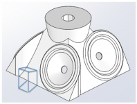
If you could add an extra block or lip to the edge where there is some space then you could attach the plastic part to the wooden extension with mechanical fasteners.
By using a wooden wedge on the back of the horn you would have two flat surfaces and make it much easier to attach, glue or gasket could be used for a tight seal.
You could either screw through or use bolts and insert nuts in the wood.
I attached some quick sketches of what I am talking about. I'm sure you could make it look nicer!
Excellent progress you have made, I think you have got me interested in synergy horn's now 😉
If you could add an extra block or lip to the edge where there is some space then you could attach the plastic part to the wooden extension with mechanical fasteners.
By using a wooden wedge on the back of the horn you would have two flat surfaces and make it much easier to attach, glue or gasket could be used for a tight seal.
You could either screw through or use bolts and insert nuts in the wood.
I attached some quick sketches of what I am talking about. I'm sure you could make it look nicer!
Attachments

Last edited:
Wow, 3d printing opens up some really creative possibilities, every angle of every flare can be optimized and positioned so long as it fits within the physical restrictions of the 3d printer and the drivers themselves don't get in the way. I need to go back and look at the Be Radian's again and see if they are any advantage over the tried and proven BMS, or perhaps get a hold of some JBL 2430k's. I know the BMS has a more favorable flare angle(?) from the phase plug then some other designs like the B&C 250. Not sure of the Radian's and JBL's latest 2430k though. apologies, rambled a bit OT.
Really amazing progress guys.
Really amazing progress guys.
Last edited:
Those lever assisted latches are cool but the 3d printed plastic is going to have trouble supporting the forces. I would stick with nuts and bolts. Self taping screws may also have problems.
As far as printing this. I have a cube duo which I have modified to run open source hardware and software, I call it opencube. The print volume is large enough to print this as one print. I am also working on an open source 3D printer that I plan on selling, which would be able to print this in one piece.
If I had a smaller printer there is software available that would allow me to cut the part into smaller pieces to print. You could design it to be printed and assembled if you want but it isn't a requirement.
As far as oblate spheroid waveguides. There are all sorts of discussions on this site about them. Personally I think oblate spheroid waveguides give you almost all the benefits of a traditional horn with diminished drawback of a horn.
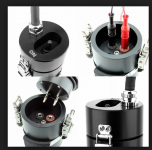
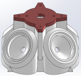
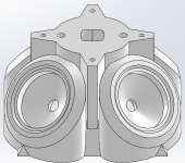
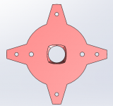
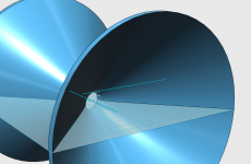
Ok, here is an idea on how to mount the CD, relying on threaded inserts which can be put in place with a soldering iron. As suggested by others, I´m using a mounting plate.
The mounting plate screws into the M6 holes in the compression driver. To avoid using a very thick mounting plate (this one is 10mm), I add holes in the remainder of the horn for the bolt heads to fit into.
Next, the mounting plate with CD is fixed to the rest of the adapter using the abovementioned threaded brass inserts. I have assumed I´ll use these ones (http://www.kerbkonus.de/proddb/pdf/en.ds.30.8640.pdf but if somebody knows a source of something similar available online in small quantities, I can change the holes to match those.


(I noticed just now that the "flares" are a bit short for the CD to fit on top, so I will make them a bit bigger later on).
Could it work?
The mounting plate screws into the M6 holes in the compression driver. To avoid using a very thick mounting plate (this one is 10mm), I add holes in the remainder of the horn for the bolt heads to fit into.
Next, the mounting plate with CD is fixed to the rest of the adapter using the abovementioned threaded brass inserts. I have assumed I´ll use these ones (http://www.kerbkonus.de/proddb/pdf/en.ds.30.8640.pdf but if somebody knows a source of something similar available online in small quantities, I can change the holes to match those.
(I noticed just now that the "flares" are a bit short for the CD to fit on top, so I will make them a bit bigger later on).
Could it work?
Attachments
Looks good! Should work!
Since you are apparently starting the horn extension in the mounting plate, you can make it as thick as it needs to be - which means you could make it thick enough to contain the heads of the M6 screws.
Jack
Since you are apparently starting the horn extension in the mounting plate, you can make it as thick as it needs to be - which means you could make it thick enough to contain the heads of the M6 screws.
Jack
As far as oblate spheroid waveguides. There are all sorts of discussions on this site about them. Personally I think oblate spheroid waveguides give you almost all the benefits of a traditional horn with diminished drawback of a horn.
Hey! I watched your reality hacking vids. Awesome!, especially the 2nd one. Just about enough to get me to buy a printer, but which one???? What do you think of 3Dmonstr?
A quick test on whether the future is already here would be to contact the people at Autotech in Poland. It takes too long and costs too much to buy a (oblate sphereoid) waveguide from them. How about if instead we just license an STL file from them and print the waveguide here!
I have used these type of threaded inserts before
Threaded Inserts
Most RC Model shops stock something similar, these are better than the wood only type as the outside thread would grip better in the plastic. They just screw in with either an allen head or flat screwdriver depending on the type. This would avoid having to thermoset the plastic.
As I have just mounted a lot of these the easiest way to get them square is to put the bolt through the hole first and then thread the nut on the bolt and it guides it through square. Use a bolt with short thread of the same diameter to make it easier.
That only works for through holes though.
while tedious I have actually used the cone primitive and sliced it to give a hyperbolic face, then rotated the face, shelled the solid to get a OS waveguide solid in free 123D Design from AutoCAD
lack of written documentation, obscurity of actual hard numerical dimensioning in 123D Design put me off going further with it
but the point is there is no need to license such a simple to generate shape as a rotationally swept hyperbola with free solid modeling tools available today
lack of written documentation, obscurity of actual hard numerical dimensioning in 123D Design put me off going further with it
but the point is there is no need to license such a simple to generate shape as a rotationally swept hyperbola with free solid modeling tools available today
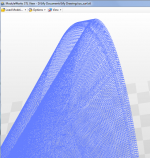
looks like I lied - I actually constructed my own cone from a 2d triangle so I could know its apex was at 0,0, then offset z by 1 unit(inch)......used the cone primitive...
tried finding angle for throat but gave up doing it inside 123d - used GeoGebra to find the scale factor, slice displacement for given throat diameter and angle
turns out that the "coarse" stl output setting from 123d is ridiculously fine
Attachments
Last edited:
Hi JCX:
You already see its not that easy. How much is your time worth?
My question was whether the state of the art had progressed to the point where someone could simply download the horn to a 3D printer ala the old Startrek matter synthesizer. When this is a reality for mainstream objects, changes will ripple throughout the economy.
I also wonder if one could do a 3D scan of a waveguide and print a copy out and, if so, would it be rugged enough for a one-off design. A 3DMonster machine that can print 18" cube is just over $4K. Probably would take a very long time to print...
Which of these free 3D CAD tools is worth learning? I've downloade 123D and FreeCAD but have barely had time to turn them on. I can do Sketchup but it looks like the hard way to do waveguides.
Jack
- Status
- Not open for further replies.
- Home
- Loudspeakers
- Multi-Way
- Synergy horn - 3d printing entry?