@nc535: I thought about what you said, and I think ABEC should show this clearly - if the mids are too far out, the sound won´t sum constructively as you mentioned.
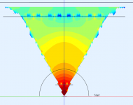
So I rendered fields to check (mids only, fake phase plug in place)
1.1kHz

1.3kHz

Directivity:

The two bright spots in the two first pictures near the mid entries are just artifacts from the transition between two subdomains. The same with the strip of blue spots at the top, where the flare angle changes.
It does seem like there is constructive summing at 1300Hz, with that midrange distance. (7.5cm at a 60x60 horn).
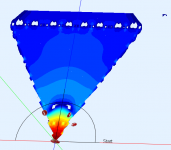
For fun, the 1450kHz field looks like this:

A strong cancellation due to the reflection of the horn throat and compression driver.
So I rendered fields to check (mids only, fake phase plug in place)
1.1kHz
1.3kHz
Directivity:
The two bright spots in the two first pictures near the mid entries are just artifacts from the transition between two subdomains. The same with the strip of blue spots at the top, where the flare angle changes.
It does seem like there is constructive summing at 1300Hz, with that midrange distance. (7.5cm at a 60x60 horn).
For fun, the 1450kHz field looks like this:
A strong cancellation due to the reflection of the horn throat and compression driver.
Attachments

![2015-01-17 20_15_28-VacsViewer - (new) - [Directivity].png](/community/data/attachments/418/418513-9e9883add061f5694886919d3d01e025.jpg?hash=npiDrdBh9W)
Thanks Kessito - quick question - how would you divide it? into horn segments perhaps? so that the parts close to the throat has higher resolution?
Yes, so à first part with the throat, a second part with the middle of the horn and a third part with the mouth.
If you send me your model I can show you how I would do it (just post the txt files here)
Last edited:
Ok, I did some changes that are encouraging:
1. Moved the mid entry points to 86mm, measured axially.
2. replaced the M10s with the 3F325s as recommended.
* 30ml as under the cone volume.
* An additional spacer of 73mm diameter and 1cm tall.
* Frustum entry 73mm -> 15mm over 16mm (just the thickness of the wood i´ll probably use, but can be anything since this is to be 3d printed).
* 0.1l as rear volume per mid. The driver itself takes up 0.125l.
Result, compression driver. The dip is shifted down to 780Hz, which means that the interference from the midrange entry holes is less of an issue.

Result midrange, with the Faital instead of the Visaton: Looks very nice!

But here´s the big surprise. The sum:

No crossovers involved here! Just the raw drivers simulated output.
Combined phase, after correcting for distance:

Here´s the mid excursion chart. Keep in mind that driving this sim is 2.83VRMS, and the charts always show peak values. I haven´t figured out how to make the charts show RMS values yet, but I suppose for excursion peak is a better thing to look at anyway?

The top peak at 230Hz is at 0.12mm, while the bottom "peak" at 370Hz shows 0.064mm. I´m not sure I have used ABEC correctly to get these values, as they seem really tiny. Perhaps Kessito has some tips for me? I will post the script in my next post.
1. Moved the mid entry points to 86mm, measured axially.
2. replaced the M10s with the 3F325s as recommended.
* 30ml as under the cone volume.
* An additional spacer of 73mm diameter and 1cm tall.
* Frustum entry 73mm -> 15mm over 16mm (just the thickness of the wood i´ll probably use, but can be anything since this is to be 3d printed).
* 0.1l as rear volume per mid. The driver itself takes up 0.125l.
Result, compression driver. The dip is shifted down to 780Hz, which means that the interference from the midrange entry holes is less of an issue.
Result midrange, with the Faital instead of the Visaton: Looks very nice!
But here´s the big surprise. The sum:
No crossovers involved here! Just the raw drivers simulated output.
Combined phase, after correcting for distance:
Here´s the mid excursion chart. Keep in mind that driving this sim is 2.83VRMS, and the charts always show peak values. I haven´t figured out how to make the charts show RMS values yet, but I suppose for excursion peak is a better thing to look at anyway?
The top peak at 230Hz is at 0.12mm, while the bottom "peak" at 370Hz shows 0.064mm. I´m not sure I have used ABEC correctly to get these values, as they seem really tiny. Perhaps Kessito has some tips for me? I will post the script in my next post.
Attachments
-
![2015-01-18 17_51_26-VacsViewer - (new) - [SPL].png](/community/data/attachments/420/420435-1995115bdd44360490e9d191e1b36381.jpg?hash=GZURW91ENg) 2015-01-18 17_51_26-VacsViewer - (new) - [SPL].png28.2 KB · Views: 1,002
2015-01-18 17_51_26-VacsViewer - (new) - [SPL].png28.2 KB · Views: 1,002 -
![2015-01-18 17_47_18-VacsViewer - (new) - [SPL].png](/community/data/attachments/420/420444-58e5d960d1190c6ec21d25e1a936270f.jpg?hash=WOXZYNEZDG) 2015-01-18 17_47_18-VacsViewer - (new) - [SPL].png27.1 KB · Views: 990
2015-01-18 17_47_18-VacsViewer - (new) - [SPL].png27.1 KB · Views: 990 -
![2015-01-18 17_56_09-VacsViewer - (new) - [SPL].png](/community/data/attachments/420/420460-2d01cb30db23beb6b83a8608516aa71c.jpg?hash=LQHLMNsjvr) 2015-01-18 17_56_09-VacsViewer - (new) - [SPL].png27.8 KB · Views: 1,012
2015-01-18 17_56_09-VacsViewer - (new) - [SPL].png27.8 KB · Views: 1,012 -
![2015-01-18 18_06_09-VacsViewer - (new) - [Phase].png](/community/data/attachments/420/420505-3808d1fb9549c9614e12e9d379a74e32.jpg?hash=OAjR-5VJyW) 2015-01-18 18_06_09-VacsViewer - (new) - [Phase].png26.3 KB · Views: 987
2015-01-18 18_06_09-VacsViewer - (new) - [Phase].png26.3 KB · Views: 987 -
![2015-01-18 18_08_11-VacsViewer - (new) - [Excursion mids].png](/community/data/attachments/420/420513-253f3f330d21173befe6168d5b536d25.jpg?hash=JT8_Mw0hFz) 2015-01-18 18_08_11-VacsViewer - (new) - [Excursion mids].png23.1 KB · Views: 971
2015-01-18 18_08_11-VacsViewer - (new) - [Excursion mids].png23.1 KB · Views: 971
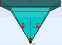
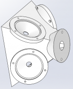
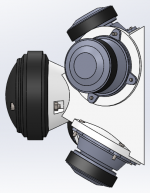
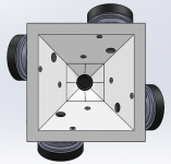
Kessito: Was this how you meant?

Yellow, aqua, teal represent individual subdomains.
The file is attached. I will attach all the files for this model a bit later, because I feel the need to clean them up - remove unnecessary comments, make them easier to read etc.
Yellow, aqua, teal represent individual subdomains.
The file is attached. I will attach all the files for this model a bit later, because I feel the need to clean them up - remove unnecessary comments, make them easier to read etc.
Attachments
Ok, I did some changes that are encouraging:
1. Moved the mid entry points to 86mm, measured axially.
2. replaced the M10s with the 3F325s as recommended.
* 30ml as under the cone volume.
* An additional spacer of 73mm diameter and 1cm tall.
* Frustum entry 73mm -> 15mm over 16mm (just the thickness of the wood i´ll probably use, but can be anything since this is to be 3d printed).
* 0.1l as rear volume per mid. The driver itself takes up 0.125l.
Result, compression driver. The dip is shifted down to 780Hz, which means that the interference from the midrange entry holes is less of an issue.
Result midrange, with the Faital instead of the Visaton: Looks very nice!
But here´s the big surprise. The sum:
No crossovers involved here! Just the raw drivers simulated output.
Combined phase, after correcting for distance:
Here´s the mid excursion chart. Keep in mind that driving this sim is 2.83VRMS, and the charts always show peak values. I haven´t figured out how to make the charts show RMS values yet, but I suppose for excursion peak is a better thing to look at anyway?
The top peak at 230Hz is at 0.12mm, while the bottom "peak" at 370Hz shows 0.064mm. I´m not sure I have used ABEC correctly to get these values, as they seem really tiny. Perhaps Kessito has some tips for me? I will post the script in my next post.
Nice work! I also like to use injection ports located about same place (89mm) and your cone displacements are correct. The horn loading is good so the driver diaphragm doesn't hardly move. When mine is running at 100dB I can touch the driver and barely feel it moving - about 40um for my 3FE22 in the tractrix horn (as main tweeter/mid driver).
Great work on new xo response.
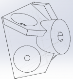
Ok, almost done.
As for the chart above with the summed response: The CD model used has this strange dip, around 1300hz. As I mentioned before, I´m not sure which one it actually is, but it is calibrated. So unless the acoustic properties of a DE250 are very different, it should be possible to use this design.
STL also included, if somebody wants to check it for printability.


I should probably make the space for the CD nuts tight enough so you don´t have to stick something in there to hold it still while tightening.
Now, if anybody could suggest a fool-proof method of fixing this to a wooden horn, I could add the necessary bits on the adapter.
As for the chart above with the summed response: The CD model used has this strange dip, around 1300hz. As I mentioned before, I´m not sure which one it actually is, but it is calibrated. So unless the acoustic properties of a DE250 are very different, it should be possible to use this design.
STL also included, if somebody wants to check it for printability.
I should probably make the space for the CD nuts tight enough so you don´t have to stick something in there to hold it still while tightening.
Now, if anybody could suggest a fool-proof method of fixing this to a wooden horn, I could add the necessary bits on the adapter.
Attachments
Last edited:
Well it has a couple overhangs that won't print without support.
And it is too big for my buildplate.
But you could design it different to make it easier to print.
In what program did you design it in?
Can you attach the original file?
Meshmixer generated the following support to make this design printable.
And it is too big for my buildplate.
But you could design it different to make it easier to print.
In what program did you design it in?
Can you attach the original file?
Meshmixer generated the following support to make this design printable.
An externally hosted image should be here but it was not working when we last tested it.
Very nice. Tooling could be made to injection mold this and pump them out for $5 ea. 🙂 totally injection molded synergy using glass filled nylon or polycarbonate may be a reality now.
Very nice. Tooling could be made to injection mold this and pump them out for $5 ea. 🙂 totally injection molded synergy using glass filled nylon or polycarbonate may be a reality now.
I have quite a bit of experience designing injection-molded parts, if you do get to that point. There are considerations with molding that you don't have to worry about with 3D printing, but if you want to make a large quantity it can be very cost-effective.
I just took a look at the file and the overhangs aren't terrible, they could be printed with a reasonable amount of support. You could also add a few parts to make it print without support. I could print this on my printer but it going to be a very big and long print. Personally, I wouldn't want to invest in printing this unless you were 100% sure it was as good as possible.
I am wondering if this design could be improved a bit more. The beauty of 3d printing is that curves are easy. A simple thing I see is that instead of the hard corners internal to the horn, you could add a fillet and smooth it out a bit. You could also put a radius on the midrange hole openings. A few others have mentioned that you could model a smooth transition, instead of the two step transition. I think this would be a worthwhile endeavor.
If you were the one doing the printing, this would be something you could do through an iterative design process. Since you don't have that as an option I would do everything you can to bring your design to perfection before printing it.
I would love to see a similar design based on an oblate spheroid waveguide that has no straight sides. I know that is outside the scope of this thread but it would be cool to see.
It can be designed as five parts or more that bolts together.
Midrange holder can be a separate part making them modular.
That way trying phaseplugs and shapes of the fructum would be simpler.
Hornshape one part. Or more if the buildplate is to small.
Mounting plate for the compression driver one part.
Then that mounting plate can be build so that the surface that touch the compression driver is the surface that touching the buildplate.
That will give it a smooth flat surface.
I'm on my fourth 3d printed waveguide
Check out my threads on diymobileaudio
I'll be posting a build thread today
Check out my threads on diymobileaudio
I'll be posting a build thread today
I'm on my fourth 3d printed waveguide
Check out my threads on diymobileaudio
I'll be posting a build thread today
Tried to find them; how about a link?
Some interesting bits from Tom Danley himself if you have not already seen this. I had but came across it again today.
Question about Danley Sound Labs 50's or 60's
Question about Danley Sound Labs 50's or 60's
thirdman, thaks for link!
Psycho Killer(Patrick Bateman)😀, did you post the build thread to diymobile?
Psycho Killer(Patrick Bateman)😀, did you post the build thread to diymobile?
Here ya go. This is my fourth synergy horn this month.
250 - A Sweet Front Stage On The Cheap. - Car Audio | DiyMobileAudio.com | Car Stereo Forum
These printers are kinda addictive, because it's really compelling to make changes to the model and re-print it.
When you're working in wood you can't just say to yourself "i'm going to move this part by half an inch." But with a printer you can. It's been really hard to settle on a final design.
But check out the polars, they're probably the best I've ever attained at the crossover point. In all of my Synergy horns I've always struggled to avoid a dip at the xover. The printer facilitates the use of very small drivers and superior phase plugs, and that helps the crossover a lot.
- Status
- Not open for further replies.
- Home
- Loudspeakers
- Multi-Way
- Synergy horn - 3d printing entry?