Hi Patrick
A few observations on 3D printing
I would not go less than 1/8" -3mm for a wall thickness You will find the prints get very fragile I found that at 2mm or less the walls split too easily while 3mm was robust.
Are you printing in PLA or ABS? I Have mostly printed in ABS. With ABS it is easy to bond and repair your prints with some scrap ABS dissolved in acetone to make some glue.
Like you I have had prints fail during printing. Sometimes I have measured what has printed and sliced it off the model to make a repair part which I have then bonded with the ABS glue.
Good to see that your model is quite detailed. You can really put lots of detail in the model and the printer will just replicate it.
I have had some rapid manufacture parts professionally printed in the past and the results were very good. Cost was quite high but it was still a bargain compared with other manufacturing methods.
cookie and Jack, I've also done some testing a couple years ago with some 4" Celestion TF0410MR with offsetting the port vs centered. I came to the same conclusion I believe..........I'll see if I can find the data.
That ABEC sim is really cool! I need to learn how to run that..........
That ABEC sim is really cool! I need to learn how to run that..........
Cookie:
I did the same center vs offset hole experiment in the lab with a driver mounted over a hole through a large baffle board and got the very similar results. This led me to implement what I called a "top hat" phase plug (attached). The plug is hollowed out to duct the sound from the center hole over to the edge. The internal path length ends up being 3-4 cm long which probably means it needs to be simmed and optimized.
The phase plug improved the worst of it but I'm now trying some 6" drivers that I have on hand to see if the end result is better.
Jack
Neat stuff. Is that top hat a flat with a depression for the dust cap clearance or is it a ring? Can't tell from photo but assume it is the former. Is the central duct then angled to get the outflow located at an offset location?
top hat phase plug details
Its a depression to avoid hitting the dustcap at high SPL. I'll attach some better pictures.
I made a truncated cone by clamping a round piece of 1/2" MDF in the arbor of my table saw, using the saw as a lathe. I then drilled a 1 3/8" dia hole down through the center and mounted the 1/4" thick top hat 1/4" above it. I mounted the assembly on 1/2" spkr mtg plate which then mounts on the horn wall. The spkr mtg plate is cut away under the hole thru the phase plug and above the holes through the horn wall to form the duct. The plug itself is hollowed out above the cut away in the spk mtg plate. So the net of this excavation is a duct that is angled on top, following the cone profile and flat on the bottom. A dremel tool with a flapper sander was invaluable in doing this.
The first picture is a top view from closer up. The 2nd picture shows the view looking up through the cut away in the speaker mounting plate.
Attachments


Last edited:
@ winslow: Thanks. Why do you think this is? Due to the resonance of the hole being at a higher frequency?
@nc535: good to hear you got the same results. I am wondering if a simple longer frustum would do the trick. the longer the frustum, the smaller the wavelength distances for the woofer. naturally, resonance will be an issue though. one thing i thought about was basically splitting the woofer into segments (say 4 slices of a pie) by an X-shape extending down into (but not touching obviously) the cone. that should help separate the waves from each section from eachother. I´m sure there are many ways of doing this, the goal must be to do it as simple and sturdy as possible, and keep it printable. 🙂
@xrk971: Thanks! Look forward to seeing your akabak-equivalent. Is there any chance btw you could help with the cone profile of the mid driver (if you still have one?)? And also - a verification of the port size for the port(s) used for the Synergy Tripp, so I don´t have to reinvent the wheel on that one. I suppose the port size is based the smallest you could get away with without too much air velocity?
Perhaps I don't see it right but it seems to me an X shape wouldn't help. Its fruitless to keep waves from different sections apart because they ultimately have to come together at the holes through the horn wall. The tophat idea was to have all the waves come together in the very center of the volume under the cone, which minimizes/reduces max delta path length difference. The separate top hat piece blocks the waves coming off the dust cap from taking a short cut directly down into the collection hole, giving them a length more like that taken from the cone edges.
BTW I think the 6" driver of choice may be the 6NDL38. Augerpro did some measurements on it a few years back that turn up in a google search (they aren't on drivervault). They are impressively smooth and have an Xmax of 6 mm. I would be buying some except that a couple of years ago I stashed 12 Aura NS6s certain that I'd eventually find a use for them.
Cone profile for XRK's 6" mid is posted in the first SynTripp thread.
I will certainly share it as long as there is no intention to use it for anything but DIY. However, i have not yet revisited the midrange choice. I think the comments I have received by others here make me think it might be beneficial to go for a variant that can dig a bit deeper, and perhaps one where I can adjust the rear cavity. So I will not fine tune the model using the M10. It´s been rather busy lately, with some home projects and work getting in the way - but I´ll see if I can pick up that part of it this weekend, trying to sim a different driver and modeling the right STL file for it.
I might take you up on your offer to print my model later too - let me just get it completed. Perhaps you can help us understand the limitations in printing slopes etc? I was trying to avoid overhangs more than 45 degrees - does this apply to all 3D printers, for instance?
Avoiding overhangs as much as possible is always a good idea but sometimes they are needed. Don't limit your design solely on this aspect as support structures are easy to add to get a good quality print.
Different print processes do not have this issue but the most affordable and most common form of 3D printing is FFD, which does have this limitation.
@ JZatopa: Ok, good to know. I will relax the requirement.
@ nc535: Thanks! I will read through the thread and find it.
I tried to run the simulation with two 70mm holes offset by 60mm. So same offset distance as the single offset, and same total area.
Perhaps result is not too surprising: Somewhere between the two first trials.


@ nc535: Thanks! I will read through the thread and find it.
I tried to run the simulation with two 70mm holes offset by 60mm. So same offset distance as the single offset, and same total area.
Perhaps result is not too surprising: Somewhere between the two first trials.
Attachments
![2015-01-13 21_31_33-VacsViewer - (new) - [SPL].png](/community/data/attachments/411/411878-e83f9b9a52b8d52070dd91af28b20225.jpg?hash=6D-bmlK41S)

Good to know that two holes is better than one 🙂
I am running my 6MDN44 with a two hole (actually sausage shapes slots). Works well up to 1khz. I will try to sim the 10CL51 with an infinite baffle and 60liter rear chamber and centered and offset slots in akabak when I have some time. Wondering if the fundamental modes in the driver front chamber are transverse and can be approximated with linear lumped element segments or should I use radial segments (pie) or azimuthal segments (donuts)?
I am running my 6MDN44 with a two hole (actually sausage shapes slots). Works well up to 1khz. I will try to sim the 10CL51 with an infinite baffle and 60liter rear chamber and centered and offset slots in akabak when I have some time. Wondering if the fundamental modes in the driver front chamber are transverse and can be approximated with linear lumped element segments or should I use radial segments (pie) or azimuthal segments (donuts)?
Two offset holes seem better than one offset hole. One centered one is even better -- everything else equal of course.
I am not sure how I would go about getting the modes calculated in Akabak -- if you figure out a rule of thumb, it would simplify ABEC use alot, because then you can start out with a BEM model of a small part of the model, make a LEM equivalent, and hide that part in the LEM section, reducing solving time by 99,9% for that part and still getting good results. Akabak and ABEC are as I mentioned 99% compatible LEM-wise.
I am not sure how I would go about getting the modes calculated in Akabak -- if you figure out a rule of thumb, it would simplify ABEC use alot, because then you can start out with a BEM model of a small part of the model, make a LEM equivalent, and hide that part in the LEM section, reducing solving time by 99,9% for that part and still getting good results. Akabak and ABEC are as I mentioned 99% compatible LEM-wise.
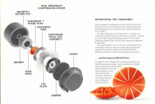
Can you model a phase plug like JBL CMCD?
I know you can, but would you mind trying?
http://www.jblpro.com/ProductAttachments/CMCD_TechNote.pdf
I have a flashforge creator dual 3D printer and enough 3fe25 to build myself a synergy horn. I also own two bms 4550, so I love this topic!
I know you can, but would you mind trying?
http://www.jblpro.com/ProductAttachments/CMCD_TechNote.pdf
I have a flashforge creator dual 3D printer and enough 3fe25 to build myself a synergy horn. I also own two bms 4550, so I love this topic!
I one want to make the transition from round entry to square horn, Spaceclaim have a really nice feature called Blending.
Blending - Futurescape
Too bad it`s not free software.
Blending - Futurescape
Too bad it`s not free software.
If you are using Solidworks it is built in. Use the "Lofting" tool in sheet metal. Make a square profile and round profile separated by height. Choose Loft shape and it blends it based on how many "panels" or regions of a bend you want.
YouTube has lots of tutorials on this.
YouTube has lots of tutorials on this.
@Nissep: Yes, I think so, but I´ll need to have a mockup of a reasonable mid driver first. So either I´ll have to buy some that others have used (i´m not competent to read through spec sheets to find suitable candidates), or somebody will have to volunteer with the cone profile for the mid. Do you think a phase plug is necessary for a 3 inch mid? I wouldn´t think so. But that mid looks interesting - I suppose since I want a three way, mostly for the challenge, I could go for something along that size. I have a feeling a tiny bit smaller driver will make the 3D printing even simpler. Did you test that driver for fit in a Synergy horn?
@fudce: Looks nice - wouldn´t want to claim that my idea was even remotely similar. I had a go with what I suggested, and it didn´t work (forgot who warned me). But the tangerine variant interesting, and it looks printable too.
@nissep: I agree with x - if you use regular lofting features, you can get an exact profile match - i think most solid modelling software should have that feature. Do a google search for "QTWG whitepaper", it explains the profile in simple terms.
I could provide you with the profile of 3fe25 and i have even started to 3D model a CMCD with this driver in sketchup.
I'm going to clean it up using Spaceclaim before show it to the world.
But i need some directions on what design criterias to follow.
Equal patchlenght might be one depending on what wavefront we like to have.
But, area for the slots close to the cone?
Distans from cone to phase plug?
Expansion on the slots?
I read somewhere that Danley did not recommend the commersial unit (CMCD) due to the wavefront leaving it.
So we need to make it better..
Bwalso mentioned that this driver have potential, thats good enough for me to try.
But I have own a couple of them before i started to collect everything i need for a synergy horn.
Conevolume is 30ml (measured with sugar)
I made some measurments with it playing thru different size holes with the back closed of with a small enclosure and 300-1000hz works great.
The only thing i have not tried is the actual hornloading.
But hornresp sim is done and looks good.
Its cheap, great sensitivity and a really nice driver.
If anyone understand Swedish they can find some of my measurment here: faktiskt.se • Visa tråd - DIY Unity och Synergy horn
Last edited:
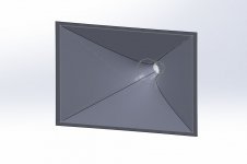
A loft in Solidworks does not require the sheetmetal feature.
The loft can be built from sketches positioned along the horn path each containing the cross section profile.
The loft can be built as a thin feature with a wall thickness suitable for the 3D printer
A nice feature is the tangency between the profiles.
This example is built from 3 profiles 2 round and one rectangular
The profile sketches could be any shape. Maybe in this example of a transition from round to rectangular the second profile should be elliptical? It should be possible to guide the loft so that the end shape is tangential to any timber horn extension used. Need to play with this a bit longer!
It would be easy to share STL files for printing by hosting them on a CAD website such as Grabcad.
Attachments
I haven't read the whole thread so forgive me if you guys have found a solution, but my 'flatmate' (the geek living in the flat downstairs) has just got a 3D printer and keeps asking me what to do with it - as I understand it's still sitting in the box.
I'll check the specs and get back to you guys if you want to have a go at getting some cheap printing done
I'll check the specs and get back to you guys if you want to have a go at getting some cheap printing done
A loft in Solidworks does not require the sheetmetal feature.
The loft can be built from sketches positioned along the horn path each containing the cross section profile.
The loft can be built as a thin feature with a wall thickness suitable for the 3D printer
A nice feature is the tangency between the profiles.
This example is built from 3 profiles 2 round and one rectangular
The profile sketches could be any shape. Maybe in this example of a transition from round to rectangular the second profile should be elliptical? It should be possible to guide the loft so that the end shape is tangential to any timber horn extension used. Need to play with this a bit longer!
It would be easy to share STL files for printing by hosting them on a CAD website such as Grabcad.
You are right, I forgot because I used the sheet metal feature so that it could be un rolled into a flat sheet ao that I can make it with thin foam core. One could make it out of sheet metal I suppose. But yes, conventional machining does not require sheet metal loft.
3FE25 is a great driver but for horn loading the 3FE22 has a stronger Nd motor and lower Qts for more control.
3fe22 vs 3fe25 on my 60x40 380hz synergy.
An externally hosted image should be here but it was not working when we last tested it.
- Status
- Not open for further replies.
- Home
- Loudspeakers
- Multi-Way
- Synergy horn - 3d printing entry?