An observation about corner horns - they don't have to be as big as freestanding horn because the corner extends the horn walls, at least horizontally. By making it as big as you plan, the primary benefit is extended vertical pattern control, which is really a secondary consideration, given that sound within the pattern will still eventually hit the floor and ceiling. You will get the corner support for your woofers regardless of the horn size. But as I have found, that corner support might not exist below 30 hz or so depending on wall construction.
So if you are having second thoughts about making a horn so large, just look at the how large the gap or step will be between the horn flare and the wall and make sure that you have pattern control down to where that is perhaps 1/4 wavelength, perhaps placing some absorber there. Of course the box has to be large enough to fit all the woofers, which might make it quite large after all.
Despite what I said the general rule that horns should be as large as you can stand or have room applies. Its really a personal choice. So have fun and I will continue to enjoy your story.
Hi nc535
Thank you for your advice/comment!
Well, I am lucky not to be restricted by aesthetics, and the corners collect dust anyway. My living room is for audio, not a show-room.🙂
And I guess I believe the creator of the K402MEH, that full-range-directivity is important. At least I want to see/hear for my self! And I can build big, so why not just try it!?
The other thing is, that I find it intriguing to have the whole (almost) spectrum of audio coming from one point-source-horn, only having a sub for the very low frequencies.
Steffen
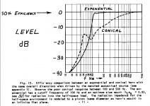
This paper by keele has a figure that I have attached which may explain why the coaxial compression driver struggles in your conic horns:
http://www.xlrtechs.com/dbkeele.com/PDF/Keele (1975-05 AES Preprint) - Whats So Sacred Exp Horns.pdf
So perhaps you should try a exponential-conic horn with the coaxial driver as you not longer need to have the mids close to the throat?
I notice that the B&C horn for their coaxial comp has a sort of similar form as well.
Attachments
This paper by keele has a figure that I have attached which may explain why the coaxial compression driver struggles in your conic horns:
http://www.xlrtechs.com/dbkeele.com/PDF/Keele (1975-05 AES Preprint) - Whats So Sacred Exp Horns.pdf
So perhaps you should try a exponential-conic horn with the coaxial driver as you not longer need to have the mids close to the throat?
I notice that the B&C horn for their coaxial comp has a sort of similar form as well.
Thx kipman,
Yeah, as i've suspected and mentioned before, i'm not sure the conical horn is really providing low end loading of the CD, where small signal measurements curve looks like the CD is OK to use. But dunno...
I'm not going to bother with trying anything like an exponential-conic horn though.
I just listened to latest syn 9 ver3.0 (haha) and think i have found something i can live with for quite a while, hopefully 🙂
(Oh, I've got the B&C horn...don't like it nearly as well as the DIY syns..)
Hi Mark
Well 4 times 12PR320´s in each side is maybe slightly overkill.😀
Hi Steffen, hey a little out door listening shows syn9 with two 12PR320's will easily keep up with 2 double 18" PPSL subs.
I really think it would be hard to make good use of 4 of the 12PR320's in a single box, even with the AXI and 4mdn34's. Unless you're planning on some major outdoor subbage.
just a couple cents to throw out 🙂
Hi Mark
Thanks for the advice and sharing of experience.
As mentioned before, I do have four 25 years old Visaton BGS38 15" woofers (Fs=40 Hz, Qts=0,30, BL=15,9, Sd=735cm2, Mmd=68g, ferrit magnet, 8 Ohm, 6 kg). And I think I will do my first horn with them, as my sketches show, that there is space for them, also when making the cabinets your way (90 degrees rotated SynergyCalc), but higher (more space for the woofers).
I am curious to see, how far down those two 15" woofers reach when in a big horn, placed further out, to cross as low as possible to a sub. As said before, I find it intriguing to have as much full-range-point-source as possible, maybe even without a sub, as Chris keeps on promoting!? I also have this idea, that it will be "easier" to create coherent crossovers for the MEH when all drivers are placed symmetrically in the same horn!?
To have four woofers in one horn is actually a way of having more freedom to place the ports, and still have the woofers positioned axially over the port-hole! But it might actually not be as necessary sound-quality-wise, when I use midranges (4NDF34)? AND ALSO the price difference between the 10PR320 and 12PR320 is not that big, so why not have the extra displacement for nearly the same money! But as said, I will start with the woofers I have.
Any comments or pictures of your SYN9 v.3? Does it work OK with two portholes under the woofers? What are the axial distances of the portholes, midrange and woofers, just to have an idea. Have you made secondary flares yet?
Good weekend
Steffen
Last edited:
Any comments or pictures of your SYN9 v.3? Does it work OK with two portholes under the woofers? What are the axial distances of the portholes, midrange and woofers, just to have an idea. Have you made secondary flares yet?
Yep, two ports for the woofers work just fine, and as you can see from the picts, they are more towards the horn walls with the ports hanging over the surrounds a bit.

The reason i previously kept the cones as close to centered over single large port, was because it raised the HF of the cone better than any other placement over the port. Now that mids eliminate the need for the woofer to play up to the CD, having the woofer cone centered over its port doesn't matter.
On the 60x60 ver2 pictured in post #33, that used a single centered port per woofer, I accidentally made the port too small (3" dia / about 11.8:1 sd😛ort).
The woofer covered 100Hz to 250Hz, and sounded a little chuffy or cardboardy on certain songs.
Now using two 2.5" ports for a 8.5 sd/port-area ratio. No chuffing at all. Truly powerful, clean, gripping mid bass.
(I keep a separate volume control on each of the 5 driver sections, where i can listen to them one at a time or in any combination. It really aids pinpointing issues on each section (and righteousness too !) ime.)
One consequence (maybe drawback, dunno) of using the top mount woofer technique, is that it forces the ports out from the horn walls the distance of the woofer mounting flanges. But for the weight savings, it's a great trade imo. (and like said, who knows if it even matters).

The woofer ports' centers are 9.5" from throat.
The mid ports are 3.5" from throat and 15/16" in dia.
Speaking of mids....you're gonna love the response of the 4mdn34s....they give so much frequency latitude to work both sides of xover points. I think they are good to use anywhere from 200Hz up to 1kHz.
Here's raw on the 75x60 ver3.

I haven't made any secondary flares yet. Not sure I will. I getting less convinced audibly, about the need for super polars once a reasonable level of smoothness is achieved. The increased portability and smaller size without secondary's, is awfully nice.
Next project will be to build a second ver3 for stereo. I'm really ecstatic over this build.
Thanks Mark
It really looks promising!
Can you show the SynergyCalc input window or dimensions HxV?
Interesting with that acidental porthole to Sd ratio experiment! You even went lower to 8,5. Any conclusions/thoughts on that? Lower extension, better efficiency?
Steffen
It really looks promising!
Can you show the SynergyCalc input window or dimensions HxV?
Interesting with that acidental porthole to Sd ratio experiment! You even went lower to 8,5. Any conclusions/thoughts on that? Lower extension, better efficiency?
Steffen
Here ya go.
First, note that H and D are swapped to be able to do the top mount config.
And it makes the horiz pattern control freq (360Hz) artificially too high.

Also note I used a 0.72 flare expansion ratio (for if i build secondary's). I've always thought the secondary's using the default 0.65 look a little big, so trying something new.
Oh, and 1.18" (30mm) is used for throat square (splits the diff between 1" and 1.4" for easier matchup, less filling in corners or carving out, to 1.4")
So the actual horn size now without any secondary's,
is width of 'C' (32.76"), and height of 'G' (24.91").

The 8.5 ratio is just a better estimate than I had before, of what's used in the SH-50
Someone posted good interior & exterior SH-50 picts recently. I also noticed the woofer ports were put in as close to the throat as would fit. Maybe that was just coincidence, and that was optimum placement despite the fit...dunno.
But I moved in towards the throat as close as the 12" would fit within the 75 deg top flare. (see top pict prior post). A 80 deg horiz would allow about another inch closer to throat still. (That assumes staying at 60 degree vertical. Can't go below 55 deg vertical and make top mount work, unless the primary horn gets REALLY big)
Extension didn't change from further out (13.5") used in 60x60 ver 2. Need to check efficiency closer, my gut says it increased from closer.
Maybe the port size change was the only real change...just dunno...but all together, the woofer SQ went up nicely. (had to, it was chuffing a little at times !!)
First, note that H and D are swapped to be able to do the top mount config.
And it makes the horiz pattern control freq (360Hz) artificially too high.
Also note I used a 0.72 flare expansion ratio (for if i build secondary's). I've always thought the secondary's using the default 0.65 look a little big, so trying something new.
Oh, and 1.18" (30mm) is used for throat square (splits the diff between 1" and 1.4" for easier matchup, less filling in corners or carving out, to 1.4")
So the actual horn size now without any secondary's,
is width of 'C' (32.76"), and height of 'G' (24.91").
The 8.5 ratio is just a better estimate than I had before, of what's used in the SH-50
Someone posted good interior & exterior SH-50 picts recently. I also noticed the woofer ports were put in as close to the throat as would fit. Maybe that was just coincidence, and that was optimum placement despite the fit...dunno.
But I moved in towards the throat as close as the 12" would fit within the 75 deg top flare. (see top pict prior post). A 80 deg horiz would allow about another inch closer to throat still. (That assumes staying at 60 degree vertical. Can't go below 55 deg vertical and make top mount work, unless the primary horn gets REALLY big)
Extension didn't change from further out (13.5") used in 60x60 ver 2. Need to check efficiency closer, my gut says it increased from closer.
Maybe the port size change was the only real change...just dunno...but all together, the woofer SQ went up nicely. (had to, it was chuffing a little at times !!)
Thanks again 🙂
" I also noticed the woofer ports were put in as close to the throat as would fit. Maybe that was just coincidence, and that was optimum placement despite the fit...dunno."
I have been thinking for a while, how to calculate for a optimal distance of the ports from the throat for a given bandwidth/frequency!? There is something about that in the patent and the DSL whitepaper on tapped horns:
https://www.danleysoundlabs.com/wp-content/uploads/2012/01/The-Tapped-Horn.pdf
BUT how to calculate that? I think I could figure out a funktion for area-expansion in respect to throat-distance and differentiate that once to find the flare-rate........maybe !? 😱
But it´s probably way easier to just build and find out, make some sawdust.
Anyways, nearer to the throat makes for a bigger overlap. And easier to linearize above crossover for your steep FIR-filters?
I learn a lot from you, thanks.
Steffen
Last edited:
You are too kind 🙂
I'm just lucky to be able to try alot of stuff easily....
Regarding 'area-expansion in respect to throat-distance and differentiate that once to find the flare-rate'.....
i asked how to calculate that right after first trying the mid ports, with no replies.
...Need horn guru help:
Would be cool to know how to do it by the math...
Hi Mark
I´ve read the thread "Need horn guru help". Maybe the thread-name is not specific enough to draw the wanted attention?
Then I have been thinking. Maybe a "picture" of an optimum axial placement of the woofer-ports for a specific woofer and a specific horn-geometri can be gained with multiple simulations in HornResp!? The idea is to simulate horns with increasing values for the axial port-hole-distance, all other input-date being the same, and evaluate/compare the corresponding results with respect to frequency-response and maybe other relevant things, to see, what distance yields the optimum response.
I have a hunch, that "one chart fits all (woofers)" doesn´t work here, and that you do have to do the work for a specifik woofer and horn!? Dunno.
I have not had time to try the idea my self, but maybe more experienced HornResp-users can do a quick check?
Steffen
Last edited:
I would use that curve as to get a starting point for port placement in an HR simulation. I think its good enough for that if you then simulate in HR. Once you have that HR simulation, its easy to vary port placement to find what works best. Finally you will confirm with measurements as simulation is not 100% accurate. Even then its not too late as wood horns can be patched and re-drilled. Still, its easier to do your cut and try in simulation.
I would use that curve as to get a starting point for port placement in an HR simulation. I think its good enough for that if you then simulate in HR. Once you have that HR simulation, its easy to vary port placement to find what works best. Finally you will confirm with measurements as simulation is not 100% accurate. Even then its not too late as wood horns can be patched and re-drilled. Still, its easier to do your cut and try in simulation.
Hi Jack, i haven't used HR for MEHs for a while now.
Some of the reasons I stopped (as best i remember), where the inability to specify port locations with regard to horn wall centers vs corners, the inability to specify multiple ports, and what seemed like an inability to make any valid predictions for the CD.
I follow the HR thread continually and know updates to the MEH capability/wizard have been made. Can it do port placement locations now?
One interesting realization lately about woofer ports, is that maybe i don't care so much about optimum loading. By optimum loading i mean ports that provide true horn loading and increase efficiency.
Maybe i care more about keeping the woofer ports within 1/4 WL of the mid ports at xover frequency between woofer and mid.
With a LR 96dB/oct xover at 300Hz between woofer and mids, i get i care about 1/4WL summation overlap to at least 350Hz (about a -20dB summation point.)
Or 9.7" quarter wave.
With mid ports at 3.5" from throat, and a 9.7" mid-port to woofer-port maximum, seems like i need to keep the woofer ports within 13.2" of the throat, no matter where optimum loading exists.
If i want to also play with more shallow slope acoustic xovers such as 2nd order(which i do), -20dB summation would take summation needs out to about 1kHz, for only 3.4" woofer-ports to to mid-ports. Clearly undoable.
Relaxing to -12dB of 1/4WL summation overlap, gives a 5.6" distance, or only 9.1" from woofer-port to throat (still using 3.5" mid port distance.)
Plus, there's also the issue of the woofer ports needing to stay within 1/4 WL of each other, as they move out the horn wall. Which becomes the quicker to occur limitation for wider pattern horns.
I guess i'm saying, maybe it just makes sense to get the woofer ports as close in as possible,..... optimum loading / modeling be damned ..???
I have a hunch, that "one chart fits all (woofers)" doesn´t work here, and that you do have to do the work for a specifik woofer and horn!? Dunno.
Yep, i think a curve for each horn pattern is clearly needed...like what mefistofelez was doing in his post #2 reply in the 'horn guru help needed' thread...
Hi Jack, i haven't used HR for MEHs for a while now.
Some of the reasons I stopped (as best i remember), where the inability to specify port locations with regard to horn wall centers vs corners, the inability to specify multiple ports, and what seemed like an inability to make any valid predictions for the CD.
I follow the HR thread continually and know updates to the MEH capability/wizard have been made. Can it do port placement locations now?
One interesting realization lately about woofer ports, is that maybe i don't care so much about optimum loading. By optimum loading i mean ports that provide true horn loading and increase efficiency.
Maybe i care more about keeping the woofer ports within 1/4 WL of the mid ports at xover frequency between woofer and mid.
With a LR 96dB/oct xover at 300Hz between woofer and mids, i get i care about 1/4WL summation overlap to at least 350Hz (about a -20dB summation point.)
Or 9.7" quarter wave.
With mid ports at 3.5" from throat, and a 9.7" mid-port to woofer-port maximum, seems like i need to keep the woofer ports within 13.2" of the throat, no matter where optimum loading exists.
If i want to also play with more shallow slope acoustic xovers such as 2nd order(which i do), -20dB summation would take summation needs out to about 1kHz, for only 3.4" woofer-ports to to mid-ports. Clearly undoable.
Relaxing to -12dB of 1/4WL summation overlap, gives a 5.6" distance, or only 9.1" from woofer-port to throat (still using 3.5" mid port distance.)
Plus, there's also the issue of the woofer ports needing to stay within 1/4 WL of each other, as they move out the horn wall. Which becomes the quicker to occur limitation for wider pattern horns.
I guess i'm saying, maybe it just makes sense to get the woofer ports as close in as possible,..... optimum loading / modeling be damned ..???
No HR can only do port locations in terms of their axial distance from the throat
HR is a "1p" simulation - one dimensional. It calculates response for an axisymmetric horn of the same crossectional area of your design. Thus it can't shed light on the in the corners vs out on the flares issue.
HR as 1p simulation is clearly an approximation but it gets certain things right - like axial distance of port location, effect of port length and area, and particle velocity in the port. That to me is worth knowing prior to making sawdust. Its a damn sight more valuable than the chart in the Danley white paper!
If you want more, you can do a 3D drawing in a CAD tool like Fusion360, mesh it, and then simulate in ABEC3. That may require climbing two learning curves and then waiting a long time for the simulation to complete.
I think that despite its limitations, HR would give you useful feedback about proposed port locations and crossover frequencies and slopes. As to loading effect, at first glance that appears to be an efficiency issue that you can just throw power at but if that were all their was to it, then Mark would not have heard such an improvement from adding the small mids. If you do a bandpass simulation of your woofer ported into your horn, you can infer loading from HR's acoustic impedance graph but in truth its included in the sound power graph. I agree loading is a 2nd priority. Both 1/4 WL rules come first.
You are correct HR won't predict the CD's response. In most cases, we can't even get T/S models for the CD. Even with them, there are issues of what kind of wave front they produce, exit angles, HOMs, modelling of the round to rectangular conversion in the throat... Even ABEC3 has limitations in this regard, as has been discussed in the ATH thread.
Thank you for the nice, big picture overview, of HR's modeling assumptions, capabilities, and limitations.
(Must admit, hearing them plainly laid out makes me feel OK with not being in to modeling so much.)
My thoughts as to why i've heard such an improvement adding the small mids are still confined to some probable modulation reduction.
I know from plenty of experience how bass and mid-bass can clean up dramatically when split between sub and woofer.
Seems like the same phenomenon has to occur higher up the spectrum, ....all throughout the spectrum really.
So it makes sense to me that relieving the CD of some lower-end duty, would help clean up it's response. Seems like reducing carrier excursion for higher frequencies just makes common sense for cleaner sound.
I'm speculating intermod distortion is a bigger deal than commonly thought.
My guess is the historical difficulties in tying together increased numbers of ways with flat mag and phase, has masked audible improvements in splitting up the spectrum.
I think you've done enough of these you know where to put the ports without even breaking out your slide rule🙂 I thought I was still talking to steff when I posted
Paul Klipsch was a big proponent of horns and one his biggest arguments was reduction of IM... If you look at the formula in his paper, that is especially important in a wide bandwidth horn because there is a frequency term in it.
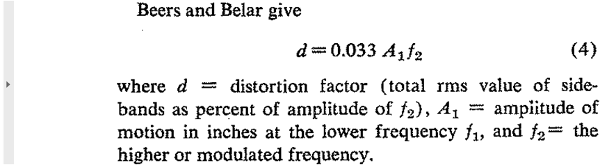
Paul Klipsch was a big proponent of horns and one his biggest arguments was reduction of IM... If you look at the formula in his paper, that is especially important in a wide bandwidth horn because there is a frequency term in it.
Attachments

Hi mark100,
perhaps you could approach the problem form a different angle (pun intended). That is, with the per-determined 1/4 wavelength distance(s), select an angle of the horn/wave-guide that satisfies both requirements.
But, then one needs the loading curves for the different angles. I see if I can find my old Maple to install and revisit the problem.
Kindest regards,
M
One interesting realization lately about woofer ports, is that maybe i don't care so much about optimum loading. By optimum loading i mean ports that provide true horn loading and increase efficiency.
Maybe i care more about keeping the woofer ports within 1/4 WL of the mid ports at xover frequency between woofer and mid.
With a LR 96dB/oct xover at 300Hz between woofer and mids, i get i care about 1/4WL summation overlap to at least 350Hz (about a -20dB summation point.)
Or 9.7" quarter wave.
. . .
I guess i'm saying, maybe it just makes sense to get the woofer ports as close in as possible,..... optimum loading / modeling be damned ..???
perhaps you could approach the problem form a different angle (pun intended). That is, with the per-determined 1/4 wavelength distance(s), select an angle of the horn/wave-guide that satisfies both requirements.
But, then one needs the loading curves for the different angles. I see if I can find my old Maple to install and revisit the problem.
Kindest regards,
M
Last edited:
- Home
- Loudspeakers
- Multi-Way
- SYN 9: a change in direction