AAK said:Hi Mike,
Thanks for the info on the soundcard setup.
I'm actually playing symasym right now. First impressions, incredible! They sound beautiful. I'll break them in over the weekend, and get back to you after I do some serious listening. Of course I think It's safe to say that the amp I used to do all those measurements probably needs a well deserved break.Thanks for all your help!
Al
Hi Al, any news ?
BTW, could you show FFT-plots as image ?
Mike
Hi Mike,
Nothing new on the symasym front to report on. Just been way to busy with work since Monday. Huge demo Thursday. Should have some news by the weekend.
For the FFT plot, with Spectraplus how do I create an image?
Al
Nothing new on the symasym front to report on. Just been way to busy with work since Monday. Huge demo Thursday. Should have some news by the weekend.
For the FFT plot, with Spectraplus how do I create an image?
Al
You can create screenshot of active window by pressing ALT+Print, this creates a copy of the window into the clipboard. Photoshop or m$-pain(t) can easily create an image from that.
Mike
Mike
Hi Mike,
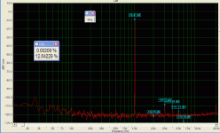
I spent some time last night trying find a way to take a THD screenshot with Spectraplus with no luck. I tried Alt+print and nothing happend, couldn't find any bitmaps. Any ideas? I'm using the free 30 day demo version with only two days left. Maybe the demo version doesn't allow screenhots. But, I was able to get the signal generator to work simultaneously with THD measuring about 0.002% at 1khz/-10db.
Al
Al, the "ALT print" is a function from windows. After you pressed that open the program "paint" (mspaint.exe) and just paste (ctrl-v). There is your screenshot.
Mike
Mike
Hi darkfenriz.
It appears to be an aliasing artifact. I had Spectraplus sample rate setting at 44.1 Khz which has a frequency limit of Fs/2 of 22.05Khz. If I set it to 48Khz, the spike goes away.
Al
It appears to be an aliasing artifact. I had Spectraplus sample rate setting at 44.1 Khz which has a frequency limit of Fs/2 of 22.05Khz. If I set it to 48Khz, the spike goes away.
Al
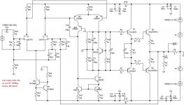
This is my modified symasym, with:
- 2sk170 (BL version) in LTP, matched at 6mA Ids
- wilson current mirror in VAS
- much linear drivers, 2sc4793/2sa1837
- good factory matched finals (mjw0302/0281)
Other modification consist in bigger tail current in LTP (Ids=3.3mA), little more VAS current than original (3.1mA), double class A drivers current (70mA) and bigger suck out capacitor (330nF)
The results are:
1kHz, 1W, 8ohm, THD 0.0009%
1kHz, 10W, 8ohm, THD 0.0031%
1kHz, 50w, 8ohm, THD 0.0074%
20kHz,1W, 8ohm, THD 0.0022%
20kHz, 10W, 8ohm, THD 0.0078%
20kHz, 50w, 8ohm, THD 0.0189%
AC phaseshift at 20Khz < 1grd
All this results are simulated with LTSpice. I want to build it but first I need your expert opinion.
Thank you,
Mihai
1kHz, 1W, 8ohm
Attachments


Hi Mihai, good work!
I see one minor problem, Q12 has to dissipate 250mw, this could be too much, or at least it will run very warm/hot. You might use a bd139 here.
Another suggestion: As you doubled the LTP-current, you might half R21/22 and reduce R18. (for symetrical clipping)
I guess, you should build it.
Mike
I see one minor problem, Q12 has to dissipate 250mw, this could be too much, or at least it will run very warm/hot. You might use a bd139 here.
Another suggestion: As you doubled the LTP-current, you might half R21/22 and reduce R18. (for symetrical clipping)
I guess, you should build it.
Mike
MikeB said:...
Another suggestion: As you doubled the LTP-current, you might half R21/22 and reduce R18. (for symetrical clipping)
I guess, you should build it.
Mike [/B]
Thank you Mike
I already done that.
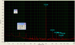
r21/22 = 340ohm, r18 = 72ohm and guess what 😀:
1kHz, 1W, 8ohm, THD 0.00088%
20Khz, 50W, 8 ohm, THD 0.01821%
AAK said:Hi Chris,
I'm working on it. I'll provide a schematic with the actual part numbers, and BOM. Also gerbers for top, bottom, and silk for those interested in building there own. The PCB program that I used is called Ivex, they went out business about three years ago. The program is very easy use, much easier than eagle, but not as powerful. I'd be glad to email the .exe plus provide any help necessary for those who would like to modify the board.
But, before I provide all this info on this forum I'd feel better emailing it to Mike so he can go over it to make sure everything is Ok for others to build.
As you can see from the pic, the board is very compact (5"x3") requiring the output and vas transistor to be mounted to the heat sink under the board. It can be a little tricky. I'll also provide some simple assembly instructions.
Best regards,
Al
Ready to go public with the layout? Getting the ps close to the amp seems like the right direction.
Sheldon
- Status
- Not open for further replies.
- Home
- Amplifiers
- Solid State
- Symasym - the sequel