anatech said:Hi Sheldon,
I don't think having the PS directly on the board is too helpful. Mike effectively does that with the local filter/bypass caps.
-Chris
I may have misintrepreted, but the Bob Cordell ps thread seems to indicate some benefit for close coupling of the supply caps and output.
Regardless, it's a compact layout and I like that. He also seemed to be getting very nice results. That may have nothing to do with the caps but it would seem to indicate a good overall layout.
Sheldon
anatech said:Hi Sheldon,
I think good layout trumps supply location any day of the week. 😉
-Chris
Seems reasonable. So let's convince AAK to post the layout, and we can have both a good and compact layout.
Sheldon
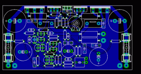
After having built my first pair of SymAsym I couldn't resist to try a slightly modified pcb layout. This is what it looks like at the moment.
- original Symasym 5.3 circuitry, went for BC550C as input diff pair
- metal foil output emitter resistors
- size: 100 x 50 mm
- single sided
- no wire bridges
- no vertical resistors
- short feedback path
- original Symasym 5.3 circuitry, went for BC550C as input diff pair
- metal foil output emitter resistors
- size: 100 x 50 mm
- single sided
- no wire bridges
- no vertical resistors
- short feedback path
Attachments
Hi all,
No, you don't have to convince me. I said I'd give you a PCB and here it is. Where I work we've been in survival mode since mid October and things have been pretty tough lately.
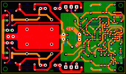
Anyway, the PCB in the pic is a new revised version that includes two components that where left out of the original board layout because of lack of space. Luckily I was able to figure a way to squeeze them in without changing things to much and keep the original dimensions and all traces minus the feedback trace on the bottom of the board.
I'll follow up with gerbers and drill files shortly. The parts numbers labeled on the amplifier part of the board is according to Mike's schematic found here.
http://www.lf-pro.net/mbittner/Sym5_Webpage/symasym5_3.html
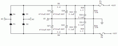
I'll also follow up with a schematic of the PS section.
Attachments
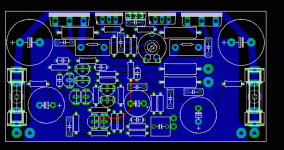
HBarske said:Feedback path colored red.
Comments welcome.
Turn the input pair 90 degrees clockwise - this would allow more phsical clearance between input and feedback traces as well as avoid having the feedback trace so near the pinouts of the 1st transistor. Of course it would mean moving maybe some parts a bit to accomodate...
Cheers!
I gave it a try:Turn the input pair 90 degrees clockwise
Attachments
Hmmm, that's still fairly tight... didn't realize there'd be a trace that would block a nice clear path to the FB resistor...
One other comment - the feedback takeoff point would be better placed right at the point the drive signal enters the output 'resistor' (the one paralleled with the output inductor. Equalizing trace lengths from the emitter resistors may also help reduce distortion...
Cheers!
One other comment - the feedback takeoff point would be better placed right at the point the drive signal enters the output 'resistor' (the one paralleled with the output inductor. Equalizing trace lengths from the emitter resistors may also help reduce distortion...
Cheers!
Hi HBarske,
There are times a jumper makes a lot of sense. Try using one to move your feedback route.
-Chris
There are times a jumper makes a lot of sense. Try using one to move your feedback route.
-Chris
I was going to say the same thing 🙂
But I was considering that the intent was to have a board without jumpers at all...
Cheers!
But I was considering that the intent was to have a board without jumpers at all...
Cheers!
Hi all,
For those wanting to build SymAsym using my board layout, whether it's Mike schematic or mine you'll have to make some changes to several resistor values to maintain thermal stability. Since the drivers are not mounted on the heatsink you'll need to change R26 to 150ohms to keep the driver stage from entering thermal runaway. I also changed R8,R9 to 100ohms, and R1,R2 to 10 ohms. You'll find this same driver EF configuration with these values on some Randy Slone amps and the very well known AKSA.
Now if you want run SymAsym at +/-50V rails like I did you'll have to change Q1/Q2 to 2N5551. I also changed Q7,Q8 to an 2N5551, but the BC546B on Mike's schematic should work fine.
If you use the drivers (2SC4793/2SA1837) and output transistors (2SC5200/2SA1943) that I used, change C14 to 10pF or less to keep the amp from oscillating. Pavel found the same thing but I believe he used different drivers.
http://web.telecom.cz/macura/symasym.html
Lastly, the output transistors are mounted to the heatsink below the board, and the thermal transistor (T1,BD139) is mounted to an output transistor. Post #77 has a picture.
Any question, feel free.
Hi nando,
To answer your question on which one to build. For a two channel amp I'd build Mikes. It's been tested by many, and you have the option to use a heftier power supply. Know, if your looking to build a home theater amp, than you might want to consider my design. It's was designed for that purpose. The board only measures 3"x5" including the PS so you can easily put two amps on one heatsink like a Conrad #MF35-75. Wiring to the board is easy, you just connect the transformers two ACs, and center tap to the board and your set. No fussing with a bunch of wires from seperate PS like you'd have in a home theater amp. Hope this helps.
Best regards,
Al
Hi Al,
Nice short signal paths. Have you built one up yet?
Hi Clem,
There are times when a jumper free board causes more trouble than it solves, as I'm sure you know. I'll go for a jumper or few anytime they shorten signal paths and improve performance.
-Chris
Nice short signal paths. Have you built one up yet?
Hi Clem,
There are times when a jumper free board causes more trouble than it solves, as I'm sure you know. I'll go for a jumper or few anytime they shorten signal paths and improve performance.
-Chris
Nice one, Al, but some thoughts:
Your power transistors are underneath the board. You will have to mount them on the heatsink first, then fiddle their wires through the holes in the pcb and then solder them. What if you ever need to take a look at the board's bottom, for example if the amp isn't working properly right from the start? Desolder all power devices?
Your power transistors are underneath the board. You will have to mount them on the heatsink first, then fiddle their wires through the holes in the pcb and then solder them. What if you ever need to take a look at the board's bottom, for example if the amp isn't working properly right from the start? Desolder all power devices?
Hi anatech,
No I haven't built this new revised version yet. The difference between this version and the previous which I tested and based all my measurements on is minimal. All I did was add R13, and C14. R13 was added by standing it in front of the input transistor Q1 as you see on the board. And R5 was moved to where it is now to make room for C14. These changes shouldn't make a difference, but I do plan to build a couple more boards for my home theater systems hopefully within the next couple weeks. I'll check to make sure everything measures up and report the results.
Hi HBarske,
To answer your question.
"What if you ever need to take a look at the board's bottom, for example if the amp isn't working properly right from the start? Desolder all power devices?"
You'll have to desolder the output devices. I made the pads with copper on both sides and through, and just large enough so that it makes it easier to remove the solder. You'll need a good desoldering tool plus some needle noise pliers to free up pins that may stick to the side of the hole. Building this board is not for the novice builder.
One thing I could do is flip the output transistors (the emmiter and base on the board) so instead of having the mounting holes underneath the board they now overlap the board by about 1/2". You'll need a taller heatsink, about 4.25" instead of 3" but now you can easily place and remove the board.
If anybody's interested, I'd be glad to make the changes.
Al
- Status
- Not open for further replies.
- Home
- Amplifiers
- Solid State
- Symasym - the sequel


