Heres is what I suggest you do (no load connected to the output)
1. Power up the amp
2. set the lab PSU to 0V and connect it to the input (the amp is DC coupled) through a 10k resistor
3. Adjust the lab PSU voltage up slowly while monitoring the output voltage of the amp. It should increase linearly with the input voltage
4. Given what you have noticed with the sine wave output, when the output jumps to the V+ rail, stop adjusting the lab supply
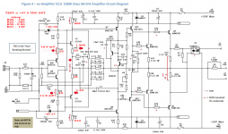
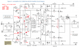
5. Now measure all the voltages marked in RED on the circuit diagram plus the voltage drops per post #2646 above
Repeat the above procedure but setting the lab supply so the amplifier output goes negative (if the supply is fully isolated, you can just swap the + and - leads to the input)
Hopefully at this point we can then try to isolate the issue.
1. Power up the amp
2. set the lab PSU to 0V and connect it to the input (the amp is DC coupled) through a 10k resistor
3. Adjust the lab PSU voltage up slowly while monitoring the output voltage of the amp. It should increase linearly with the input voltage
4. Given what you have noticed with the sine wave output, when the output jumps to the V+ rail, stop adjusting the lab supply
5. Now measure all the voltages marked in RED on the circuit diagram plus the voltage drops per post #2646 above
Repeat the above procedure but setting the lab supply so the amplifier output goes negative (if the supply is fully isolated, you can just swap the + and - leads to the input)
Hopefully at this point we can then try to isolate the issue.
Thanks. I have run the tests, and here are the results. Before you responded I changed back R28,R29,R36,R37 to the original spec'd values of 15R, to test, but made no difference either. But I left them in place during this test. Also here is the input to output voltages at different levels, I was able to run up the voltage to within 1V of the rails during both tests.Heres is what I suggest you do (no load connected to the output)
1. Power up the amp
2. set the lab PSU to 0V and connect it to the input (the amp is DC coupled) through a 10k resistor
3. Adjust the lab PSU voltage up slowly while monitoring the output voltage of the amp. It should increase linearly with the input voltage
4. Given what you have noticed with the sine wave output, when the output jumps to the V+ rail, stop adjusting the lab supply
5. Now measure all the voltages marked in RED on the circuit diagram plus the voltage drops per post #2646 above
Repeat the above procedure but setting the lab supply so the amplifier output goes negative (if the supply is fully isolated, you can just swap the + and - leads to the input)
Hopefully at this point we can then try to isolate the issue.
.24 = 4.90
.75 = 14.57
1.15 = 21.83
1.55 = 29.26
2.12 = 40
2.45 = 45
2.75 = 47
Thanks again for the help,
Attachments
hi,
Your voltage around R28, 29, 36 and 37 are not right. The resistor values should be 150 Ohms for R36 and R37 and 120 Ohms for R28 and R29. The standoff voltages across R36 and R37 should be c. 145mV and across R28 and R29 about 150mV each.
With the 15 Ohms values you have used the input diamond buffer transistor Vbe differences can result in one of more of the devices switching off which would cause the problem you are seeing. By raising them to 150 and 120 Ohms, the Vbe differences are swamped by the emitter degeneration resistor stand off voltages and the front end is well behaved from the signal and thermal aspect.
What does the PCB silk screen say for these values?
I have Rev 1.0 boards, SS says 15 ohms as does original BOM. I had 120 and 150 ohm resistors in there before with same results.
wow - you must have very early boards. The silk screen and BOM was changed waaay back. Please return the amps to the 150 and 120 Ohms. Can you down load the latest build doc here (can you confirm its a nx and not sx amp you are building?)
http://hifisonix.com/wordpress/wp-content/uploads/2020/02/The-Ovation-nx-Amplifier-V2.10.pdf
http://hifisonix.com/wordpress/wp-content/uploads/2020/02/The-Ovation-nx-Amplifier-V2.10.pdf
Yes they are V1.0 around 2013 ish. I have the updated BOM, I will replace the 15 ohm with 120 and 150 ohm and retest the voltages. It is a NX amp. Thanks
OK - can you then repeat the test, but measure the voltages across R28 and R29 and across R30 and R31 with each increment of the input voltage. Seems one half of the amp is turning off. You will need to do this with a -ve going DD input signal as well.
Here is the +DC input voltages, I will get -DC input voltages this afternoon. ThanksOK - can you then repeat the test, but measure the voltages across R28 and R29 and across R30 and R31 with each increment of the input voltage. Seems one half of the amp is turning off. You will need to do this with a -ve going DD input signal as well.
Attachments
Let me look at this again tomorrow- I’ve bern busy today.I've ordered Rev 2.0 PCB's and expecting delivery soon, I may just start from scratch.
Ok no worries. ThanksLet me look at this again tomorrow- I’ve bern busy today.
Please can you recheck the voltages at the emitters of Q9 and Q11. wrt 0V (assuming you have dialled the amplifiers output offset to 0V) these should read about 0.15V. if you measure across the R28 and R29 you should get the same voltages. Are the voltages you measured not at the bases of Q9 and Q11?
Can you take you meter and measure the value of R23, R22, R31, R30 - must all be 15 Ohms. R33 and R32 - 1k. (
Can you tell me what the DC input voltages were that you input to get the output - just the max values for 47V output for both + and -?
If I look at your voltages, on the +ve swing, the VAS standing current collapses above 45V - you can see this because the voltage drop across R33 and R32 drops off which means the VAS current will also collapses - its almost as if the hFE is dropping right off. Are Q8, Q9, Q10 and Q11 all ok - did you get them from a main stream disti?
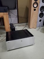
After many years with many build issues, I have Ovation NX operating in my system this entire evening. Dead Quiet, Stunning sound!
Thank You Bonsai!
After reading the last few posts here, I realized that I have 2013 boards so need to examine a few things along with cleaning up wire routing, but man it sounds like a very expensive amp.
Thank You Bonsai!
After reading the last few posts here, I realized that I have 2013 boards so need to examine a few things along with cleaning up wire routing, but man it sounds like a very expensive amp.
Attachments

In the new BOM for NX, KSC3503DS and KSA1381ESTU can be used. Old BOM states that these two devices need to be the same gain grade.. Curious as to why this change is suitable and not problematic?
- Home
- Amplifiers
- Solid State
- SX-Amp and NX-Amp