Here is the voltages from 1 amp board, and yes both are doing the exact same thing. I have ordered KSC3503D from digikey to swap out the 2SC3503 to see if that makes a difference. With no load the amp still will not go full rail voltage, the scope behavior is the same as with the load like the image I posted before.The gain on that looks a bit low (I get ~108). But, you also don't know how the device is behaving as the Vce increases as ther amp output swings between the two rails. The +ve side spike almost loops like the device is 'snapping' to some kind of short circuit mode.
I earnestly recommend that you never ever buy parts off eBay - always stick to mainstream disti's like Mouser, Digikey, RS etc. You do pay more, but you know what you are getting.
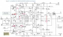
Below is a circuit diagram - you should check all your quiescent DC voltage against this with no input signal.
If the voltages are all ok, try please try this:
1. Connect the PSU to the amp (especially the Zobel connections - do not leave these off. Make sure the wires to and from the amp module are tightly bundled together
2. Run the amp with no load and a 1kHz input signal and see if it swings up to the rails - if it does, I would suspect the driver gains are dropping off at higher currents load currents. Check the 0 Ohm jumpers - make sure they are 0 Ohms and have not been damaged and gone high R during assembly.
Come back and let us know what you have found (are both channels behaving like this?)
Thanks!
Attachments
Also forgot to add. The DC offset swings from -6mV to +4.5mV, not sure if this is normal behavior either.
Yeah so how were the voltages? Should I just wait now to swap the transistor?The DC offset will typically settle to within a few mV of 0 V after about 2-3 mins.
The voltages so far look ok. Can you check the voltage drop across R22 and R23 and R30 and R31.
Thanks, here is the voltage drops;The voltages so far look ok. Can you check the voltage drop across R22 and R23 and R30 and R31.
R22 - .542
R23 - .542
R30 - .400
R31 - .401
VAScurrent=26mA?Thanks, here is the voltage drops;
R22 - .542
R23 - .542
R30 - .400
R31 - .401
Those readings are all ok. Indeed as Thimios notes, VAS current is 26 mA.
I think you should wait until your new VAS devices are installed before doing any more tests.
I think you should wait until your new VAS devices are installed before doing any more tests.
Changed the 3503's with New from Digikey, they only had D grade, but still the same exact issue, so that wasn't the problem, is there a chance its a board issue?
Highly unlikely- about 50 or 60 of the V1 boards were sold.
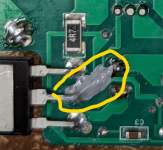
What are those small blue resistors on your the board?
What are those small blue resistors on your the board?
Sorry those are the 1k resistors, I pulled them all and verified, they are correct. I also pulled the 10k resistors and verified those as well.
Thermal compound as recommended to help bias track with temp.
Any thoughts on what I should check next?They look like NTC’s to me. I should have said something earlier about it.
I think the only way we can try to get to the bottom of this is to inject a DC input and look at the amp voltages with no load connected to the output.
Have you got a lab PSU where you can adjust the voltage that we can use to inject a DC signal?
Have you got a lab PSU where you can adjust the voltage that we can use to inject a DC signal?
I will have one today. What voltages should I test at and what I'm I looking for. Thanks!I think the only way we can try to get to the bottom of this is to inject a DC input and look at the amp voltages with no load connected to the output.
Have you got a lab PSU where you can adjust the voltage that we can use to inject a DC signal?
- Home
- Amplifiers
- Solid State
- SX-Amp and NX-Amp