Power toroids have no winding separation so rely entirely on varnish for interwinding insulation. Something to consider when abusing them.
Shoog
Shoog
"Power toroids have no winding separation so rely entirely on varnish for interwinding insulation"
Yup, and this bothers me a bit, at least when it comes to interleaving windings from two transformers.
Yup, and this bothers me a bit, at least when it comes to interleaving windings from two transformers.
In order to comply with safety regulations, primary and secondary windings need a safe insulation barrier (thus more than varnish, typically a PETP film) between them. Depending on the regulations, two primaries might also need additional insulation means
Hi-pot test 4kV doesn't mean anything?
Also, secondary is grounded and wound on top of primary. A Pri-sec short will blow a fuse.
Also, secondary is grounded and wound on top of primary. A Pri-sec short will blow a fuse.
I believe the 4kV hi-pot test is done between primary and secondary? I assume there is some kind of insulation tape between primary and secondary windings. What (hypothetically) bothers me is the risk for insulation breakdown between the primaries at large voltage swings. The primaries are usually bifilar wound, right? I believe you when you say your amps with interleaved toroids work fine, but this is still causing a bit of headache. Maybe it´s just me being paranoid here, if pri-pri insulation breakdown was a common thing noone would sell mains transformers with dual primary windings.
I would take a C meter and measure primary to secondary capacitances ( short each tested winding with clip leads ). Then check between the two primary windings. Then check a toroid that does not perform well for audio OT use. Maybe one can predict whether other toroids will work well by capacitance.
I have some Signal Corp 24VA E-I xfmrs, DPC-12-2000 (6.3V, 6.3V ) 50-60 Hz which measure:
Pri1 - Pri2 255 pF
Sec - Sec 111 pF
Pri - Sec: 149 pF, 150 pF, 285 pF, 157 pF ( the 285 pF is probably the secondary closest to a primary )
Leakage inductances:
Pri1 to both Sec shorted 8.37 mH
Pri2 to both Sec shorted 13.46 mH
Pri1 and Pri2 parallel to both Sec shorted 1.75 mH
Pri1 to Pri2 shorted 4.81 mH
I would guess the two primaries have insulation between them here. Signal Corp is usually top notch on specs. 1500 V Hipot test.
Last edited:
If you short the two primaries, you get a silence machine with B+ on both tubes. I still don't see how anything could "break"...
I feel your pain and share your concern. The two 120 volt primaries were intended to have 120 volts between them, not 240. The varnish can only do so much. How much can it take? And does a lot of mechanical stress (magnetostriction) make things worse? I guess building amp and subjecting it to ghetto bass for hours would be one way to find out. Far different use conditions than playing hi-fi quietly at home.I believe the 4kV hi-pot test is done between primary and secondary? I assume there is some kind of insulation tape between primary and secondary windings. What (hypothetically) bothers me is the risk for insulation breakdown between the primaries at large voltage swings. The primaries are usually bifilar wound, right? I believe you when you say your amps with interleaved toroids work fine, but this is still causing a bit of headache. Maybe it´s just me being paranoid here, if pri-pri insulation breakdown was a common thing noone would sell mains transformers with dual primary windings.
The Antek HV trafos seem to be ok putting the secondaries in series for a 2-diode center tapped rectifier. They do run up to 500-0-500. The big 950-0-950 is really two separate 475-0-475’s, individually taped so it doesn’t go to 950 volts between turns (that would be crazy). That’s quite a bit more than 120 volts between adjacent turns, but it would have been designed with that in mind. The trafos cost more per VA than their low-volt ones, so it’s probably an extra heavy build on the wire. All the other toroid power and OPT makers have got to be doing the same thing. But would you trust the 120 volt bifilar windings to be able to take 475 volts between them in any given run of the mill toroid?
It won’t explode, but I’ll bet the tubes will red plate after a while driving a zero ohm load.If you short the two primaries, you get a silence machine with B+ on both tubes. I still don't see how anything could "break"...
Except why would you leave it like that? I dunno about you, but if I expect sound and there isn't any, I bench it 🙂It won’t explode, but I’ll bet the tubes will red plate after a while driving a zero ohm load.
There is often a delay between when an amp/cabinet goes out and when an operator shuts it down.
I guess so. I was thinking more like listening in your own room rather than a stage or whatever. In any case, tubes working into a short will try and pull more power which a fuse could be fitted to protect against, no?
There is definitely a vast difference between home hifi and stage/PA use, yes. I could probably live with the interleaved toroid concept for hifi use (with a properly fused B+) but I would not rely on it in a high power instrument amp for live use. Building an 100+ W all tube bass amp is one of the projects I have in the pipeline, for this I have already wound an output transformer (1,8k:4-8R) on a double C core from an old Siemens power supply. An ambitious project and a rather stupid one too, I already have at least three bass amps and the one I use the most is about the same size as that output transformer, weights a lot less and delivers 200W thanks to SMPS and class D technology. Might as well use my homemade OPT for a tube subwoofer amp instead...🙂
Back to topic: I just found a few 400VA toroids with 2*115V primaries and a whole bunch of high current/low voltage secondaries for 15Euro each...in Germany, "pickup only". If someone in Münich reads this and wants to give them a try, send me a PM.
Back to topic: I just found a few 400VA toroids with 2*115V primaries and a whole bunch of high current/low voltage secondaries for 15Euro each...in Germany, "pickup only". If someone in Münich reads this and wants to give them a try, send me a PM.
If you have unwound one of these you will not find any tape between primary and secondary, or that is my recollection from last time i did it.In order to comply with safety regulations, primary and secondary windings need a safe insulation barrier (thus more than varnish, typically a PETP film) between them. Depending on the regulations, two primaries might also need additional insulation means
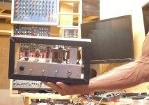
Why would I want to build a 1 KW vacuum tube amp when THIS (cabinet still not finished) is the guitar amp I use most often. It makes a blazing 4 watts which is quite loud even in a 2000 square foot basement? I'm still questioning myself about that one as I work on it.Building an 100+ W all tube bass amp is one of the projects I have in the pipeline, for this I have already wound an output transformer (1,8k:4-8R) on a double C core from an old Siemens power supply. An ambitious project and a rather stupid one too, I already have at least three bass amps and the one I use the most is about the same size as that output transformer, weights a lot less and delivers 200W thanks to SMPS and class D technology. Might as well use my homemade OPT for a tube subwoofer amp instead...🙂
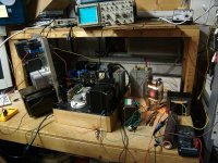
As for the vacuum tube subwoofer, I still have the 833A's, the OPT and a much smaller power transformer to build a sub or killer SE guitar amp based on this experiment I did nearly 20 years ago. I have a TI class D EVB that makes a bunch of watts (over 500 depending on configuration), so the 833A stuff will NEVER happen. The parts will be for sale at the Dayton hamfest.
Attachments
In fact, I have, and there was an insulating layer present between the primary and secondaries. It could be that different regulations apply according to the country, but in Belgium another insulation layer is always required between mains and exposed parts. I think that according to EU regulations, the requirement has even become more stringent, requiring minimal thickness of insulating materials for example, but I am now out of the circuit, and I don't follow these developments closelyIf you have unwound one of these you will not find any tape between primary and secondary, or that is my recollection from last time i did it.

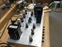
1000 maybe, but just 100+ isn’t impractical at all. It still a lot smaller/lighter than a speaker cabinet. The 200 watters started out as “the bass amp” but after listening to one for five minutes convinced me not to have it relegated to amateur-hour instrument amp duty. I ended up with a more practical 136 watts - but used standard off the shelf output trafo. The power trafo was home made (From a $15 donor core, end bells that were lying around, and maybe 5-10 bucks worth of magnet wire). All cheap off-voltage tubes - easy when winding your own power trafo. When trying to save money on transformers often the place to START is with the power trafo - solutions there are much simpler than the output trafo, even for large or very large amplifiers.Building an 100+ W all tube bass amp is one of the projects I have in the pipeline, for this I have already wound an output transformer (1,8k:4-8R) on a double C core from an old Siemens power supply. An ambitious project and a rather stupid one too
Attachments
This thread reminded me of a tube amplifier design that was popular on this forum quite some time ago. I thought it was stupid and dangerous at the time, and made my thoughts known here, but they were ignored. Fortunately, the amp didn't get built too often and faded into obscurity. The designer had recommended an off the shelf toroidal low voltage transformer in the power supply. The transformer had two 120 volt primaries that were probably bifilar wound. The builder was supposed to use only ONE of these windings for the 120 volt primary, and the other 120 volt primary as the HV secondary in a tube amp feeding a voltage doubler. The LV secondary was used to power the tube heaters. There are TWO BIG issues here. The single half primary is now asked to carry twice it's rated current, so that wire will get HOT! It is likely wound together with the other winding which is now used as the secondary with one end connected to circuit ground. The hot winding could easily short to the other nearby winding putting RAW LINE voltage on your audio ground which is connected to all of your outboard gear. Yes, your line fuse SHOULD blow, but do you want to risk your life on proper wiring?
If you ever see this being done, DON'T go there. It is generally OK to turn isolation transformers around and use them backwards, and I have done this with the Triad N-68X to get a 240 volt CT secondary, but NEVER split a primary that is intended to be used in series or parallel and try to use half of it alone. Many transformers now have a warning against this on the transformer or in the data sheet.
If you ever see this being done, DON'T go there. It is generally OK to turn isolation transformers around and use them backwards, and I have done this with the Triad N-68X to get a 240 volt CT secondary, but NEVER split a primary that is intended to be used in series or parallel and try to use half of it alone. Many transformers now have a warning against this on the transformer or in the data sheet.
Re. pri/sec insulation: I did an image search on the subject and every pictured transformer had a plastic wrapping between primary and secondary windings.
My tube bass amp project is put on ice until I can find a suitable power transformer, preferably more or less for free of course...
Plan A is to use a pair of PL519 (40KG6) or a quad of PL36 (25E5) as I have a good stash of both types, unfortunately they have quite odd heater voltages.
I´ll found something sooner or later.
I found something mildly interesting in my junk box (read: junk room) last night: a ~400VA toroid with 2*115V primary windings and a massive 77V 5A secondary plus two 9,5V low current windings. Since we´ve been talking subwoofer tube amps lately, this one tickled my imagination a bit. 80R p-p is too low for a plate coupled amp but perhaps a sweep tube PP cathode follower or a Circlotron would work? Think "OTL assisted by a 3:1 transformer for slightly better impedance matching". OTOH, limit ourselves to tubes? Perhaps a pair of big mosfets with Schade-style local feedback and/or CFB from the 9,5V windings would work wonders here?
Last edited:
Would Tubelab consider such a thing? Well there are a pair of 600 ohm SE OPT's from Toroidy waiting for my cathode follower experiments, and a few big 650 volt SiC Jfets to try in place of the tubes. I'm thinking of building a two stage UNSET board with solid state parts which I have called FETSET. See this thread:Since we´ve been talking subwoofer tube amps lately, this one tickled my imagination a bit. 80R p-p is too low for a plate coupled amp but perhaps a sweep tube PP cathode follower or a Circlotron would work? Think "OTL assisted by a 3:1 transformer for slightly better impedance matching". OTOH, limit ourselves to tubes? Perhaps a pair of big mosfets with Schade-style local feedback and/or CFB from the 9,5V windings would work wonders here?
https://www.diyaudio.com/community/threads/schade-common-gate-scg-preamp.380487/
- Home
- Amplifiers
- Tubes / Valves
- Surplus toroid transformers as OPTs...with a little twist.