These are the ones in place throughout the regulator:
https://www.mouser.ie/ProductDetail/710-860160574014
0.42R max
https://www.mouser.ie/ProductDetail/710-860160574014
0.42R max
Attachments

Hi Fran,If anyone sees anything wrong with my build, please do let me know.
Nothing wrong visually, although I recall that someone had stability issues with 100 nF rather than 100 pF at C12 - maybe just confirm that piece is the right value?

I saw that!! Yes, 100pF is there
And sense is connected to output right at the clamp terminals via wire jumpers. They are very tight to the terminals so aren't easy to see.
And sense is connected to output right at the clamp terminals via wire jumpers. They are very tight to the terminals so aren't easy to see.
@woodturner-fran I had an issue similiar to yours. I had installed the wrong size cap in the C12 position. Mine was too large and it oscillated like an oscillator, LOL. Also, the recommended Nichicon Fc series caps have about .23 ESR. What is your caps ESR?
I think your fine at .42, but someone more familiar with the circuit should answer that question.
OK, so its one step forward, two steps back.
I changed out C3 and C4 and with the OP27 this got rid of the oscillation.
So the wurth 120uF (mouser 710-860160574014) had something to do with it, and I replaced these with Panasonic 100uF (mouser # 667-EEU-FRE101). Happy with myself I thought I would move on to the neg regulator to see how it would go - I swapped C7 and C8 for the same caps. I had left the OPA1611 on this neg regulator - and it worked perfectly, no oscillation.
So then I thought I would go back, take off the OP27, and see if I replaced it with the OPA1611 what would happen - it would be good to know if this worked. Anyway, the answer is no, there is oscillation. Replaced the OP27 and no oscillation.
*************************************
So to recap, at this point, I have OP27 in the positive regulator, OPA1611 in the negative regulator, panasonic caps at the output, and LM4040diz-10 for D5 with >2mA feeding it.
I had been doing this testing at ~270mA so I thought... I better check at another current. So I replaced the load resistor with a 20R one, which would pull ~600mA - but doing so brought back oscillation. As another test - I swapped out R6 to see would the same thing happen if I went for a higher voltage (15V - which would also mean more current) so I swapped in 390R there, and yes, oscillation is there. Prodding around the back of the board with fingers changes the oscillation slightly on the scope, but that's what you would expect I suppose.
Negative regulator shows none of this.....
The regulator illustrated with the chart on the right is unstable.Just for comparison, I am attaching my two simulations, both regulators work in my audio system, serial in the amplifier and shunt in the DAC. I've mentioned both in posts before.
As I said in post 2998, convert the right axis from phase to group delay (tg). The "Q" is equal to PI * f * tg. If Q>1.3 the regulator tends towards instability. (at Q=1.3, phase margin is 40 degrees)
OK - I might have this solved but I need to test a bit more.
100uF across the power pins of the op27 seems to have cured the oscillations. I tried 22uF, and while it dropped the magnitude of the oscillation, it did not stop it. I'll test more in the coming days. I would like to see if that would also work with OPA1611, I think I will put that on an adapter board to try (I had been soldering it down).
100uF across the power pins of the op27 seems to have cured the oscillations. I tried 22uF, and while it dropped the magnitude of the oscillation, it did not stop it. I'll test more in the coming days. I would like to see if that would also work with OPA1611, I think I will put that on an adapter board to try (I had been soldering it down).
Bypassing capacitors anywhere too may cause oscillations. The pcb you are using is like the last one designed by Jan Didden?
No capacitors are bypassed, load is a resistor right at the terminals. The PCB is v2.3 from the diyaudio store a few months back....
I will try swapping back in the OPA1611 with the cap on the power pins and see if it is stable with that. I originally had the OPA1611 soldered down to the smd pads, but the op27 is in a socket. So I will put the OPA1611 on an adaptor and see if it oscillates still.
I will try swapping back in the OPA1611 with the cap on the power pins and see if it is stable with that. I originally had the OPA1611 soldered down to the smd pads, but the op27 is in a socket. So I will put the OPA1611 on an adaptor and see if it oscillates still.
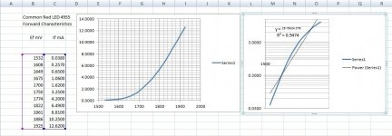
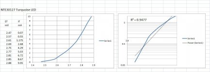
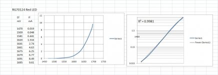
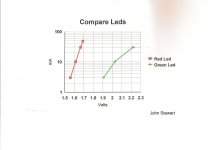
LEDs are just another forward biased SS diode & follow a square law EI curve. For the technically inclined SS diodes have a slope of 2 on a log-log graph while a vacuum diode has a slope of three halves on the same graph. And an ordinary resister has a slope of one. Tunsten lamps run around a slope of 0.7-0.8.Do not use blue or white leds … they have high noise.
The first LED I ever heard of was while interning at the U of T Physics Lab around 1959. Think it was at an RCA Lab in Pennsylvania (Lansdale?) had engineering samples of red LEDS at 50 USD a pop. We didn’t buy.
When I escaped the research lab I joined HP Sales in Toronto, by 1968 we had MIL grade red LEDs for 8USD each. The first HP LEDs used GaA (Gallium Arsenide) from Monsanto. An HP secure facility with reactors to cook Gallium Arsenide crystals was built in the Palo Alto area.
Ten years later we were selling common LEDs for 6-7 cents in quantities of a million. Packard had said he didn’t want to be in a business where the product had become a commodity. A few years later the Opto Electronic Div (OED) of HP was split off into another company,
We never talked about LED noise, they were forward biased in common use. Their reverse bias spec is very limited. But they do make a more than passable balanced mixer hooked up a ring quad! The result is Double Side Band, Suppressed Carrier output. You will find that in the 38 KHz sub carrier of analogue stereo broadcast. That is the audio thread connexion here. It is also a half way step to SSB communication systems.
All the things we don’t have to know to get thru life!
And has anyone ever measured that LED noise in a carefully controlled experiment talked about a lot here on DIY? Can we please see the results, have they been published? And why do people use a non-linear device to bias a tube?
Attachments

My results have been discussed here.
short pointer to flickr:
< >
To the right, there are more pics of regulators, Zeners etc.
Measured with Agilent 89441A and preamp that averages over 20 ADA4898 OpAmps, 220 pV/rtHz.
BTW, the pretty picture to the left is the Blau valley near Ulm, Germany. The Gauss family operates a
hotel there. Yes, the Math-Gauss.
A question that keeps me busy at the moment: Does the electrical noise and the optical noise
of a LED / vertical cavity diode laser correlate?
ed: it seems , the pic is transmogrified into diyA. You cannot escape to FLICKR. This is a misfeature.
not even in double or pointy quotes.
Make one string without blanks from this:
https: //www. flickr. com /photos/137684711@N07/24354944411/in/album-72157662535945536/lightbox/
Last edited:
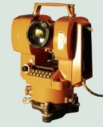
HP used the high power IREDs in equipment we sold for Land Survey & Civil Engineering. These were sourced from Monsanto.
The IRED was modulated so that the time of a reflected IR beam could be used as a measurement of distance,
Angle was measured by an optical glass disc in the base of the instrument scribed in Gray Binary code.
All microprocessor controlled. And for ~3yrs I went to work wearing Jeans, Safety Boots & a Hard Hat.
And traveled the entire country, 👍
But in this case the IRED is run in a very different mode than as a common LED in the cathode of your preamp.😀
Attachments
HP cleaved itself into many companies -- Avago, now Broadcom, was the LED biz. Keysight is the electronic test equipment, Agilent is medical equipment etc.LEDs are just another forward biased SS diode & follow a square law EI curve. For the technically inclined SS diodes have a slope of 2 on a log-log graph while a vacuum diode has a slope of three halves on the same graph. And an ordinary resister has a slope of one. Tunsten lamps run around a slope of 0.7-0.8.
The first LED I ever heard of was while interning at the U of T Physics Lab around 1959. Think it was at an RCA Lab in Pennsylvania (Lansdale?) had engineering samples of red LEDS at 50 USD a pop. We didn’t buy.
When I escaped the research lab I joined HP Sales in Toronto, by 1968 we had MIL grade red LEDs for 8USD each. The first HP LEDs used GaA (Gallium Arsenide) from Monsanto. An HP secure facility with reactors to cook Gallium Arsenide crystals was built in the Palo Alto area.
Ten years later we were selling common LEDs for 6-7 cents in quantities of a million. Packard had said he didn’t want to be in a business where the product had become a commodity. A few years later the Opto Electronic Div (OED) of HP was split off into another company,
And has anyone ever measured that LED noise in a carefully controlled experiment talked about a lot here on DIY? Can we please see the results, have they been published? And why do people use a non-linear device to bias a tube?
The first LED I saw was at an RCA lab in (I think) New Providence NJ, but much later than your experience, mbe 1966.
The option to use series LEDs as references hasn't yet been quite analyzed in this forum. Least of all build an SR and measure it to see what you get. On simulations it seems to do fine, but noise is still an issue.
Pity Jan or Walt didn't bother to comment on it. At least to positively and definitely say why it's not a good option.
Pity Jan or Walt didn't bother to comment on it. At least to positively and definitely say why it's not a good option.
Find someone with appropriate expertise and equipment (and availability/willingness), then pay them to perform the measurements you seek.
- Home
- The diyAudio Store
- Super Regulator