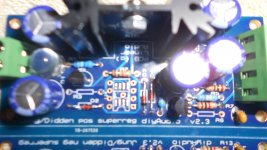
you should use metal film 1% resistors for R6, R7 , not 5% carbon films . this isn't what's wrong with your regulator , but these set the output voltage and Walt was specific about them being good quality and oversized (1/2Watt) if possible
Excuse the silly question.
Should I use a resistor to short J2 connections or will a wire jumper suffice?
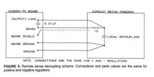
I think that Gary Galo decoupled the "sense" connections with 10Ω resistors -- this was in an article describing his modification of the Adcom GFP-565 preamplifier. I posted a picture in August 2014.
I think that Gary Galo decoupled the "sense" connections with 10Ω resistors -- this was in an article describing his modification of the Adcom GFP-565 preamplifier. I posted a picture in August 2014.
What would be the point of doing this? Does this take the sense aspect out of the circuit?
Decoupling the sense returns with a series R and some cap to ground (don't remember the values but I believe it is in the article) will stop any instability at high frequencies due to the long(ish) wire inductance.
Jan
Jan
Thanks, Mr. Didden, for the explanation.
My circuit is within two inches of the outputs so I think I have no concerns about this.
I do have one "module" working and I hear nothing that should not be there. In fact, it sounds quite good.
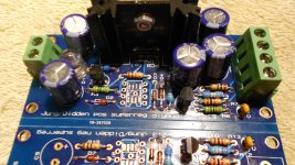
A rather OTT project - Pass complementary buffer powered by the JUNG/DIDDEN reg - A DIYAudio Store project since I am using the FETs they sell, also! Using the recommended 10uF cap and in addition shunting with 750R for each one. They are placed after a SOEKRIS DAC (raw outputs) for the moment and will also be used after a SALAS phono stage.
The channel with the buffer module does sound better. There is much more extension beyond the speaker and additional clarity I think from quietude.
The buffer drives a Slagle autoformer.
I know Mr. Pass does not think the circuit needs this kind of obsession and I did not listen to it unregulated but I think one cannot go wrong with making something as good as it can be.
I will use a second buffer on each channel to drive a Slagle 1:5 autoformer to match levels of my loudspeakers (the 100 to 500 hz channel) per Zen Mod's clever plan. At this point those autoformers are being driven by the autoformer attenuator. I expect they will be happier with a buffer between them. (there are multiple amplfiers)
Thanks for making these boards available. I thought I was a shunt only guy but, so far, I find no fault with these.
Now to get the others up and running ...
My circuit is within two inches of the outputs so I think I have no concerns about this.
I do have one "module" working and I hear nothing that should not be there. In fact, it sounds quite good.
A rather OTT project - Pass complementary buffer powered by the JUNG/DIDDEN reg - A DIYAudio Store project since I am using the FETs they sell, also! Using the recommended 10uF cap and in addition shunting with 750R for each one. They are placed after a SOEKRIS DAC (raw outputs) for the moment and will also be used after a SALAS phono stage.
The channel with the buffer module does sound better. There is much more extension beyond the speaker and additional clarity I think from quietude.
The buffer drives a Slagle autoformer.
I know Mr. Pass does not think the circuit needs this kind of obsession and I did not listen to it unregulated but I think one cannot go wrong with making something as good as it can be.
I will use a second buffer on each channel to drive a Slagle 1:5 autoformer to match levels of my loudspeakers (the 100 to 500 hz channel) per Zen Mod's clever plan. At this point those autoformers are being driven by the autoformer attenuator. I expect they will be happier with a buffer between them. (there are multiple amplfiers)
Thanks for making these boards available. I thought I was a shunt only guy but, so far, I find no fault with these.
Now to get the others up and running ...
you should use metal film 1% resistors for R6, R7 , not 5% carbon films . this isn't what's wrong with your regulator , but these set the output voltage and Walt was specific about them being good quality and oversized (1/2Watt) if possible
MMM! Thanks for picking that up ticknpop. I followed the BOM that was provided on the site when I ordered the pcbs. I foresee problems with trying to push a 1/2watt resistor through the via that has already been soldered 🙁???
I do recall reading that comment while researching the super regulators.
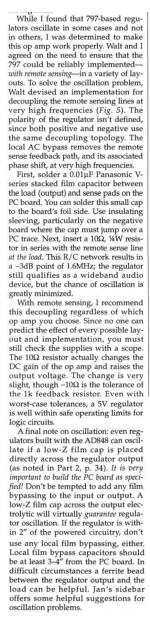
Here is the circuit schematic, and also Gary Galo's verbatim explanation, from his article (super regs part 4). Click on the "expand me to full size" white X at bottom left of the images.
_
Thanks for the helpful and informative post Mark. The learning curve is steep and the more I learn .........the less I know!
"a simple power supply for the super regs" sounds like you mean rectifiers, filter capacitors, and possibly other components, that produce filtered, but not regulated, "raw DC" as input to the super regulators.
A fairly standard design, with typical components and typical circuit topology, is attached. "S1Dot" is the phase-dot end of secondary#1 , while "S1_ND" is the no-phase-dot end of secondary#1. Secondary#2 wires are named "S2Dot" and "S2_ND". "Shield" is the transformer's electrostatic shield (purple wire on an Antek AS toroid), if present. "To_Star" is the star ground. As shown, the supply produces +28V @ 4 amps and -28V @ 4 amps. With a 500mA Jung/Didden super reg, you would draw less than 4 amps, so maybe you might modify the circuit to use smaller capacitors and scrawnier diodes.
If you decide to keep the transformer snubbers (C1, C2, R2, etc) you will need to tune them for the particular transformer you are using. Search the forum for "snubber" and/or "Quasimodo" to learn more.
Nice pcb Mark.
Where can I get one of these -
was thinking along the lines of diy pcb etching but you have changed my mind.
Do you have the dimensions of that unregulated power supply pcb? Since I intend fitting the super regs into a Marantz cd67, I am restricted by space limitations.
That's the "RingNot" PCB in post #1100. The RingNot Gerber Files that you would send to a fab to get boards made, are available for free download on diyAudio here. I myself have sent those very Gerber Files to several fabs, after getting price quotes on the spectacularly helpful website http://www.pcbshopper.comhttp://www.pcbshopper.com. PCB size is 84mm x 91mm.Nice pcb Mark.
However, keep in mind that RingNot is designed to power 2 x LM3886 "chip amp" power amplifiers, so it uses 30 amp rectifiers (!!) and 50 volt, 22000 microfarad filter capacitors (!). Both of which are unnecessarily large to power a 500mA Jung-Didden Super Regulator.
I foresee problems with trying to push a 1/2watt resistor through the via that has already been soldered 🙁???
A really good investment are some desoldering tools, solder sucker and flux.
A really good investment are some desoldering tools, solder sucker and flux.
Have them all 🙂, but still have concerns about heat damage to the pcb.
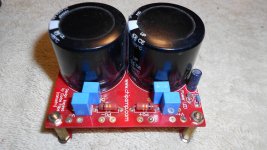
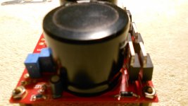
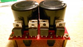
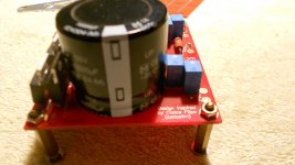
Chipamp unregulated power supply
I found this while scratching through my spare parts bin looking for metal film resistors for the super regulators. I bought it about fiver years ago from a seller on diyaudio. Would this be suitable to power the super regs? Or would it need some modification?
It is from Chip Amp and has Carlos Felipe name.
That's the "RingNot" PCB in post #1100. The RingNot Gerber Files that you would send to a fab to get boards made, are available for free download on diyAudio here. I myself have sent those very Gerber Files to several fabs, after getting price quotes on the spectacularly helpful website http://www.pcbshopper.comhttp://www.pcbshopper.com. PCB size is 84mm x 91mm.
However, keep in mind that RingNot is designed to power 2 x LM3886 "chip amp" power amplifiers, so it uses 30 amp rectifiers (!!) and 50 volt, 22000 microfarad filter capacitors (!). Both of which are unnecessarily large to power a 500mA Jung-Didden Super Regulator.
I found this while scratching through my spare parts bin looking for metal film resistors for the super regulators. I bought it about fiver years ago from a seller on diyaudio. Would this be suitable to power the super regs? Or would it need some modification?
It is from Chip Amp and has Carlos Felipe name.
Attachments

The sch I have seen for the Carlos PSU has the snubber in the wrong location.
Can you post the sch for your PCB?
Can you post the sch for your PCB?
I have a couple of these boards unpopulated. The so called CF snubber is just a RC network (1R in series of 0.1uF) across each filter cap of each rail. Not sure it is wrong location or not, but definitely not the location that I usually associate to snubber.
NYV, yes, you can use this PSU. Just connect V+ <-> PG+ to the +ve SR, and V- <-> PG- to the -ve SR.
NYV, yes, you can use this PSU. Just connect V+ <-> PG+ to the +ve SR, and V- <-> PG- to the -ve SR.
Schematics
Unfortunately the powersupply came as it is - fully assembled but without any information or schematics.
The sch I have seen for the Carlos PSU has the snubber in the wrong location.
Can you post the sch for your PCB?
Unfortunately the powersupply came as it is - fully assembled but without any information or schematics.
- Home
- The diyAudio Store
- Super Regulator