120mA is OK but if you want set higher bias replace 1k resistor in bias circuit to 1k2... nice work
Regards
I just noticed that OP is setting 120mA per transistor pair. Isn't that a bit high; would 35mA not be better (same as an SR200)?
Thank you very much! I will try.120mA is OK but if you want set higher bias replace 1k resistor in bias circuit to 1k2... nice work
Regards
I just noticed that OP is setting 120mA per transistor pair. Isn't that a bit high; would 35mA not be better (same as an SR200)?
120mA is maximum posible seting and you can set any lower value. Yes 35mA is better with small heatsink.
120mA is maximum posible seting and you can set any lower value. Yes 35mA is better with small heatsink.
Mr. Mile , could you kindly help viki_v2 on your fx-100 thread ? he has some questions regarding PSU+protect .
regards
Prasi
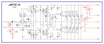
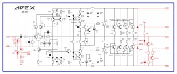
SR300
my respect to sir mile,
i made several of your SR amps and they are all at its best quality and box designs of yours too.
with SR200 - 5pairs of MJL21193-4 @90VDC i think my sub speaker was abused to use without limit which leads me think to add some limiter but my knowledge arent enough... i have copied limiter from B500.
here are the attached schematic coz i spent my leisure time in soldering, please guide me i want to make SR300 with limiter in input or even VI if you recommend some.
Next on DC overload detect at negativ rail so to ease me in making PCB layout..
thank you
regardz..
120mA is maximum posible seting and you can set any lower value. Yes 35mA is better with small heatsink.
my respect to sir mile,
i made several of your SR amps and they are all at its best quality and box designs of yours too.
with SR200 - 5pairs of MJL21193-4 @90VDC i think my sub speaker was abused to use without limit which leads me think to add some limiter but my knowledge arent enough... i have copied limiter from B500.
here are the attached schematic coz i spent my leisure time in soldering, please guide me i want to make SR300 with limiter in input or even VI if you recommend some.
Next on DC overload detect at negativ rail so to ease me in making PCB layout..
thank you
regardz..
Attachments
Would like to build it
Hello All,
I would like to build this amp. Before that thought of asking couple of queries which I have.. hope you don't mind in answering that 🙂
1. What about the sound quality difference between LM3886 based Amp vs Apex Studio Ref(of course, not in terms of power)
2. I would like to start with the PCB layout given by Alex mm. Is the layout mentioned under Post #710 latest? And also the BoM.
I really appreciate your reply. Happy time to all!! 🙂
-Sha
Hello All,Hello All,
I would like to build this amp. Before that thought of asking couple of queries which I have.. hope you don't mind in answering that 🙂
1. What about the sound quality difference between LM3886 based Amp vs Apex Studio Ref(of course, not in terms of power)
2. I would like to start with the PCB layout given by Alex mm. Is the layout mentioned under Post #710 latest? And also the BoM.
I really appreciate your reply. Happy time to all!! 🙂
-Sha
Forgot to mention the amp model, sorry for that.. I am looking for SR200.
Thank you.
Sha
SR300
Greetings...
my respect to sir mile, 44250 and all DIYers
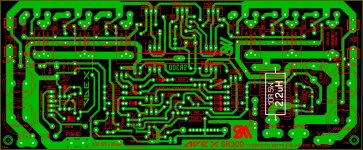
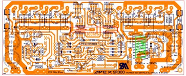
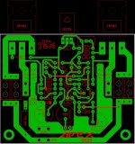
im glad to have received my 2SK2145 just today and just few more components to wait. i tried to explore sprint layout and here is my revision of PCB from 44250 and i would like to hear some expert opinion for the following:
- can i use 1 heatsink for mje's 340 and 350 (insulated from each other) about 5mm x 50mm x 50mm,
- led indicators
- Zobel and PROtect in one PCB
- are the positions of V+, 0, V- and Input, Output considerable in terms of electromagnetic effect (loop area)?
hope to hear some help... ... ... thank you,
regards,
sam
Greetings...
my respect to sir mile, 44250 and all DIYers
im glad to have received my 2SK2145 just today and just few more components to wait. i tried to explore sprint layout and here is my revision of PCB from 44250 and i would like to hear some expert opinion for the following:
- can i use 1 heatsink for mje's 340 and 350 (insulated from each other) about 5mm x 50mm x 50mm,
- led indicators
- Zobel and PROtect in one PCB
- are the positions of V+, 0, V- and Input, Output considerable in terms of electromagnetic effect (loop area)?
hope to hear some help... ... ... thank you,
regards,
sam
Attachments
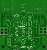
I am far far away from expert, but I usually try to avoid Zobel coil on a same pcb with an amplifier,and if it must be there - it should be located at output stage part of a pcb as far away possible from input VAS stage. second thing,when I draw a pcb i try to. make separate ground wireing of input signal and ground for large capacitors on an amplifier pcb in positive and negative side of supply. that is why i put large capacitors as near as possible to output transistors and make connecting points of plus and ground to one side of pcb and minus and ground to opposite side. also,if i use fuses,i put them before large capacitors because thin copper wire inside the fuse will act as resistor, and acting so it will decrease amount of current that output transistors need to pull out from that capacitor. my opinion about protection circuits and LED circuits on a same pcb with an amplifier is that they do not make any interference to an amplifier it self-and it does make things pretty simpler when it comes to inboxing whole thing in a casing.
I am far far away from expert, but I usually try to avoid Zobel coil on a same pcb with an amplifier,and if it must be there - it should be located at output stage part of a pcb as far away possible from input VAS stage. second thing,when I draw a pcb i try to. make separate ground wireing of input signal and ground for large capacitors on an amplifier pcb in positive and negative side of supply. that is why i put large capacitors as near as possible to output transistors and make connecting points of plus and ground to one side of pcb and minus and ground to opposite side. also,if i use fuses,i put them before large capacitors because thin copper wire inside the fuse will act as resistor, and acting so it will decrease amount of current that output transistors need to pull out from that capacitor. my opinion about protection circuits and LED circuits on a same pcb with an amplifier is that they do not make any interference to an amplifier it self-and it does make things pretty simpler when it comes to inboxing whole thing in a casing.
There is also an error in the pcb regarding the output: the power resistors (coming form the output transistors on positive and negative side) should be connected together.
There is also an error in the pcb regarding the output: the power resistors (coming form the output transistors on positive and negative side) should be connected together.
That's the old famous Mile's underboard jumper, that hasn't been shown in the drawing.
I am far far away from expert, but I usually try to avoid Zobel coil on a same pcb with an amplifier,and if it must be there - it should be located at output stage part of a pcb as far away possible from input VAS stage. second thing,when I draw a pcb i try to. make separate ground wireing of input signal and ground for large capacitors on an amplifier pcb in positive and negative side of supply. that is why i put large capacitors as near as possible to output transistors and make connecting points of plus and ground to one side of pcb and minus and ground to opposite side. also,if i use fuses,i put them before large capacitors because thin copper wire inside the fuse will act as resistor, and acting so it will decrease amount of current that output transistors need to pull out from that capacitor. my opinion about protection circuits and LED circuits on a same pcb with an amplifier is that they do not make any interference to an amplifier it self-and it does make things pretty simpler when it comes to inboxing whole thing in a casing.
your experiences makes you experts sir... and thats the big help to my learnings
i always redraw in making projects but this time i tried to explore SPRINT layout and i really had fun that is why i try to modify to save a little space on PCB to make it all in one so to ease in inboxing them but i have to ask people here since i need advises from advanced persons. and i will make a list of those things you suggested in my future references... regarding to the fuse position i was a little confused since i am referring to post #2517 but its ok you have explained it well enough.
There is also an error in the pcb regarding the output: the power resistors (coming form the output transistors on positive and negative side) should be connected together.
That's the old famous Mile's underboard jumper, that hasn't been shown in the drawing.
yes i forgot to show that one of the apex's trademark nevertheless since i have made several apex made amps my instincts often entails me to place it.
thank you
best regards
sam

@ saminnografix ; i see what you mean,and that proves that it is always easier to criticize other work than own 🙂 there are few real experts here,we all other are trying as best as we can and always learning on our mistakes...
@ saminnografix ; i see what you mean,and that proves that it is always easier to criticize other work than own 🙂 there are few real experts here,we all other are trying as best as we can and always learning on our mistakes...
no problem with that, i was expecting more comment than approval😎 I always welcome criticisms positively coz' i don't want to be subjective, i am yet a novice on this...
regards
sam
@ saminnografix ; i see what you mean,and that proves that it is always easier to criticize other work than own 🙂 there are few real experts here,we all other are trying as best as we can and always learning on our mistakes...
This thread s not about criticizing but it is about helping. And Saminnografix asked for input too. So I don't see anything wrong here.
I didn't read any bad criticism.
you missed the point, saminnografix understood what i wanted to say. there are no hard feelings, we are just exchanging experiences and I have criticised my own pcb actually...
just a few moments ago my version of pcb's came under my hand,and I have noticed that i have not cleverly rotated those MJE 340/350 so that they all can have their back sides to one heatsink as you did. i liked it and I will rotate them as you did on my sprint file, but for actual pcb's it is too late,they are already made by that file by wich you did your version. learn and share, thanks saminnografix!
just a few moments ago my version of pcb's came under my hand,and I have noticed that i have not cleverly rotated those MJE 340/350 so that they all can have their back sides to one heatsink as you did. i liked it and I will rotate them as you did on my sprint file, but for actual pcb's it is too late,they are already made by that file by wich you did your version. learn and share, thanks saminnografix!
yes, drawing is not hard for me, but really need to learn the principles too, last night i have went back to my layout, and i did turned back my predrivers too i just thought it would be very hot for four of them in one heatsink i had the experience of white smoke in underestimating predrivers on previous projects, so i pulled it back to main heatsink. i divided them equally, maybe i'll etched PCB this summer after my class.
i am attaching my new file for perusal
maybe if somebody want to suggest the value of resistors in the input if i add LDR for limiter since LED indicators are already there...thank you...
regards
sam
- Home
- Amplifiers
- Solid State
- Studio Reference Amplifier