thank you so much for the advice sir, i will then make a list of components for that 800W amp. and try if i can make such amp work.
i will first use that psu 7 for test (shown on pics) using small 42-0-42VAC trafo.
then if succed i will make PCB for PSU75. may i ask which is more reliable 2x15000uf or 3x10000uf per rail? how about caps impedance?
further, does this need to be regulated or not?
thanks,
regards
Please show as the schematic or link of your choise for that 800W amp,
maybe we can help you analyzing the schematic and find possible errors,
that is everything OK, before you start the project.
Like AndrewT already told you,
the U_out _ripple with same load would be equal with 2x15000uF or 3x10000uF bulk elkos .
But if we look the inrush currents from trafo through bridge rectifier diodes to the group of bulk elkos,
the first of identical elkos in the group/bank (who has the shortest leads/path to bridge rectifier) will suffer most inrush currents.
Good practise is use some smaller elkos in "first" place, then follow with big ones:
for example
-from trafo secondary we put the secondary snubbers, (see Mark Johnsons secondary trafo snubbers)
-then power bridge rectifier with rated voltage and current,
-then we start paralleling 1uF//100uF//1000uF//15000uF//15000uF bulk elkos in group/bank
and from the last 15000uF we then take our PSU OUT
If you look in below graph, bulk elkos bank is charged from trafo through bridge rectifier in pulses (see red pulses)
and those are very high amperage inrush currents with use of some very big bulk elkos.
R_esr*(I_inrush)^2 = P_bulk elko ESR losses and elkos will dried out faster with exaggerated losses.
So we must find ours bulk elkos with:
-nominal/rated capacitance and rated voltages
-with low ESR (10 - 20mOhms), low ESR losses
-Ripple currents @ low freq (10A @ 100Hz), those are elkos inrush currents
-Life time @ rated temp (example 5000hours@105°C)
-tolerance of rated values
The OutputPowerStage (OPS) (Drivers + Output power pairs) can be unregulated,
but input stage with VAS and predrivers if we have poor PowerSupplyRejectionRatio (PSRR)
then is almost mandatory use of good regulated PSU for that stage.
See Apex PSU75 for details :Voltage doubler with Cap multiplicator regulated +/- 85VDC (100mA) PSU
Attachments

Last edited:
Please show as the schematic or link of your choise for that 800W amp,
maybe we can help you analyzing the schematic and find possible errors,
that is everything OK, before you start the project.
Good Day sir,
i am referring to Post #977 from the Great Mr. Mile though according to him he will not give neither support nor schematic since it's his commercial product. but he positively said it's OK to clone, he further emphasized this model uses reversed engineering, that is why i ask about CCS.
i have tried B500 already which can be upgraded to H900, very powerful but i wanted to have not just power but quality that Studio reference have. this does not mean i do not like the quality of H900. BUT because i will be powering a 3way speaker system with dual 15"x600w and 2" horn.
and i will just bridge my B500 to handle 18" 8r1kw for sub.
there was a schematic made by some diyers but no further discussion bout it, i am developing a schematic and if lucky will try to make it presentable and easy to evaluate, it was almost done but i have to finish my reports so i will come back after that reports are done.
See Apex PSU75 for details :Voltage doubler with Cap multiplicator regulated +/- 85VDC (100mA) PSU
in the above mentioned model i will use MJL21193/4 OPS,
can i use 62-0-62Vac because i am thinking to use toroid trafo for SR's.
Thank you very much
regards...
SAM
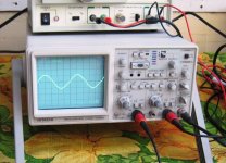
crossover distortion can only be observed accurately using a scope....
saminnografix,
keep in mind that all computations presented here
are engineering estimates.....they may or may not jibe exactly with
real life measurements....
only FTC testing of your built up amps will confirm what you really got...
this is how cross over distortion looks like on a scope...at 2.8v ac into an 8 ohm dummy load and 1khz signal input...
Attachments
crossover distortion can only be observed accurately using a scope....
saminnografix,
keep in mind that all computations presented here
are engineering estimates.....they may or may not jibe exactly with
real life measurements....
only FTC testing of your built up amps will confirm what you really got...
this is how cross over distortion looks like on a scope...at 2.8v ac into an 8 ohm dummy load and 1khz signal input...
unfortunately sir i do not have one. i used to test with the help of university professor and his scope before but this year he went to la union for his doctoral so i only use my ears in testing with Analog and Digital MM companion. i am not Electronics but i have basics of electrical course. i am a student and manage to live with my few phpeso from Electrical and Computer servicing.
besides, thank you for the advises of diyers it fertilizes me and hope to grow somehow.
regards,
sam
Good Day sir,
i am referring to Post #977 from the Great Mr. Mile though according to him he will not give neither support nor schematic since it's his commercial product. but he positively said it's OK to clone, he further emphasized this model uses reversed engineering, that is why i ask about CCS.
i have tried B500 already which can be upgraded to H900, very powerful but i wanted to have not just power but quality that Studio reference have. this does not mean i do not like the quality of H900. BUT because i will be powering a 3way speaker system with dual 15"x600w and 2" horn.
and i will just bridge my B500 to handle 18" 8r1kw for sub.
there was a schematic made by some diyers but no further discussion bout it, i am developing a schematic and if lucky will try to make it presentable and easy to evaluate, it was almost done but i have to finish my reports so i will come back after that reports are done.
in the above mentioned model i will use MJL21193/4 OPS,
can i use 62-0-62Vac because i am thinking to use toroid trafo for SR's.
Thank you very much
regards...
SAM
Hi Sam,
I see the link to post #977 and there is only PCB of APEX commercial version of SR800.
So link me those schematics of DIY-ers (or yours) schematics clones (or reverse engineering) that we can evaluate (or help) further...
Regardless to reff. post #977 the SR800 (800Wrms@4R0) wont work with 1943/5200, OK, Yes probably with 15-20pairs!!! 🙂
1943/5200 SOA curve is terrible for high U_ce voltages!!!
Your choise are MJL21193/94, and this is good starting point.
OPS must be suitable to deliver 800Wrms to 4R0 or even more problematic reactive loads!
For 800Wrms @ 4R0 we need = sqrt(800*4)*sqrt(2)=80VDC+ OPS PSU
Let us choose +/-83-85VDC
And sqrt(800W/4R0) = 14,15Arms avarage currents, peaks will be in 20-25Apeaks+ range
For this we must choose trafo with 85VDC/0,95/sqrt(2) @ max load = 62-63VAC secondaries
0,95 is 5% losses faktor @ max trafo load
choose (63+63VAC or 63-0-63VAC CenterTaped CT) and with 1,5KVA power rated for one (1) channel,
efficiency of AB Class AMP is below 0,6 or 60%, so why trafo power multiplicator is (AB Class AMP OUT Power) x2
for stereo choose 2,8-3KVA trafo,
and yes,
!!!trafo (or two of them) needs SoftStart!!!
Then we must look at OPS SOA
In MJL21193/94 TO264 200W DS we can find SOA graph
-at 85VDC we can find 2,25ADC value, and this is 85VDC*2,25ADC=190W of total dissipation power @25°C
-now we must look into Derating SOA curve if there are any...
-we can find Derating value in the first Table - Max Ratings
look at Total Power Dissipation column/line there you can find Derating faktor above 25°C = 1,43W/°C
-so in our AMP at max power we cool down OPS with suitable heatsink and the heatsink will be at 50°C, but BJT Junktion will be at 55-60°C.
-so we must consider our Derating for 60°C with Derating factor
P_max_diss@60°C = 190W@25°C - ((60-25)°C *1,43W/°C) =140W@60°C
I_max@60°C = P_max_diss@60°C/U_ce = 140W/85VDC = 1,65ADC
-Irms@800W@4R0 = sqrt(800W/4R0) = 14,15Arms
-OPS pairs we need for suiting that power@PSU and@Load
=Irms / Derating I_max@60°C = 14,15/1,62 = 8,6X OPS pairs
Better choice would be choose MJ21195/96 TO3 250W OPS devices
-at 85VDC U_ce in DS we can find 2,8ADC I_max @25°C = 238W
-Derating is with faktor 1,43W/°C
-so we get @60°C: 238W - (60-25)*1,43= 190W
-I_max @60°C = 190W/85VDC = 2,25Arms
-OPS pairs we minimum needs: 14,15Arms/2,25Arms=6,2X, so minimum choose is 6 pairs TO3 BJTs!!!
The drivers choose is:
- those worst example of 25Apeak+ current of OPS
- we must deliver to their bases with OPS devices h_fe = 10 (worst scenario see DS)
-so 25Apeak/10(h_fe) = I_max _drivers = 2,5Apeak@85VDC
-and for that we choose another 21193/94 device like driver
The pre-driver choose is:
-2,5Apeak worst scenario of drivers max loading (drivers 21193/94)
-drivers h_fe @ 2,5A is 50, so we get I_drivers_base max = 2,5Apeak/50= 50mApeak,
and this is too much for VAS load, so we must take some predrivers in TripleEmitterFollower TEF-OPS topology
-so with Ic_predrivers max=50mA on +/-85VDC PSU we can choose MJE 340/350 or similar BJTs, Uceo = 200V+, Ic=1A+, Pdiss= 5W+, h_fe = 50+
So VAS will be loaded at max with some mA for max OPS OUT Power.
And this is just suitable OPS TEF!
For SR type AMP we now need SR input stage + VAS on +/-100VDC PSU (100mA)...
...to be continued 🙂 this days!
Last edited:
Really nice analysis, but I think it would be better to have a few 200-400W amps rather than a 800W amp.
What speakers are going to take 800W avg power, at what cost? How many speakers are you going to run in parallel?
For crowds it is better to have multiple speakers/amps, just like most big PA systems, something to be said for redundancy in terms of reliability.
What speakers are going to take 800W avg power, at what cost? How many speakers are you going to run in parallel?
For crowds it is better to have multiple speakers/amps, just like most big PA systems, something to be said for redundancy in terms of reliability.
can i use 2sc3503 pair in place of sc4793 pair ?
i have to ask because i have it in stock .
Regards,
Daniel
i have to ask because i have it in stock .
Regards,
Daniel
can i use 2sc3503 pair in place of sc4793 pair ?
i have to ask because i have it in stock .
Regards,
Daniel
try comparing the data sheets sir, pin outs, etc. that is what do before changing to another.
thanks
sam,
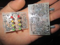
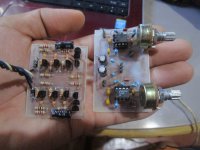
SR200
SR PP8 working good does the BD's 139/140 needs heatsink because i already did.
here are some pics and would like to have some suggestion if its ok to use.
2 x SRPP8 + OP Line amp to 2 x SR200 amp.
regards,
SAM
SR PP8 working good does the BD's 139/140 needs heatsink because i already did.
here are some pics and would like to have some suggestion if its ok to use.
2 x SRPP8 + OP Line amp to 2 x SR200 amp.
regards,
SAM
Attachments

the differents i noticed is on collector current capability,with 100ma on sc3503 and 1A on sc4793 .
can i use 2sc3503 pair in place of sc4793 pair ?
i have to ask because i have it in stock .
Regards,
Daniel
pair of 3503/1381 are low Cob 2.5pF and suitable for VAS
and pair 4793/1837 with 20pF Cob and 1A capability (look the SOA) is beter for predrivers or drivers
hi sir,
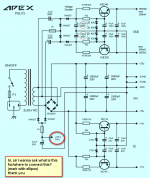
where/what in the use of +40 Pro for
thanks
+40V PRO is for protect suply... no need to be use.
PSU
thank you sir
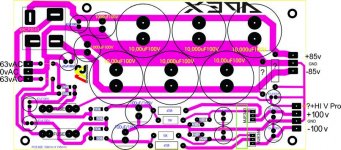
here is the PSU please see if it is correct. i will add the +/-15v on the other side later for 5pair SR.
thanks again
sam
+40V PRO is for protect suply... no need to be use.
thank you sir
here is the PSU please see if it is correct. i will add the +/-15v on the other side later for 5pair SR.
thanks again
sam
Attachments
thank you sir
here is the PSU please see if it is correct. i will add the +/-15v on the other side later for 5pair SR.
thanks again
sam
why use thin traces?, fill the damn thing with copper where ever you can... copper on the copper clad is free, why waste it? etchant (ferric chloride) isnt free either!
regards
Prasi
hi ,Sr im trying to make a apex B500 but I need the layout of the pcb can you help me ? please and keep doing what you doing good job mile thankyou
hi ,Sr im trying to make a apex B500 but I need the layout of the pcb can you help me ? please and keep doing what you doing good job mile thankyou
Go to 500W PA amplifier with Limiter
thank you sir
here is the PSU please see if it is correct. i will add the +/-15v on the other side later for 5pair SR.
thanks again
sam
thanks for noticing but i have drawn it in one stroke only, i intend not to fill it to aid checking i'm not an engr. like most of the people here--just a hobbyist, on final i will just give 2-3 mm distances (to minimize loop - as some diyers often advise).
regards
sam
- Home
- Amplifiers
- Solid State
- Studio Reference Amplifier