I just received the PCB's for my SR-200 build. I had to order 10 pieces but want keep only 4 of them. So if anyone is interested I'm selling 6 PCB's. They are designed by Alexmm and are version 3.2.
Price is 8 Euro each plus shipping.
PM me if you are interested.
Hi,
I am interested in getting 4 PCBS when possible. Let me know. Thank you. You have PM.
Best regards
rephil
Hi,
I am interested in getting 4 PCBS when possible. Let me know. Thank you. You have PM.
Best regards
rephil
PM replied.
I just received the PCB's for my SR-200 build. I had to order 10 pieces but want keep only 4 of them. So if anyone is interested I'm selling 6 PCB's. They are designed by Alexmm and are version 3.2.
Price is 8 Euro each plus shipping.
PM me if you are interested.
PCB's are sold.
I suggest to set output voltage to get 10-15V lower than input unregulated voltage. Larger difference give better voltage stability but with more dissipation.
Regards
Mister Mile, given the above, is it correct to assume that I would need a 800 VA (2 x 55 volts / 7,27 A) transformer for one channel when I want to drive 4 ohm speakers with 200 watts of output power?
The 55 volts would give me about 77 volts after rectifier and buffer caps. That leaves 12 volts higher voltage assuming I want to supply +/- 65 volts to the SR-200 amp. Is that correct?
What would be the down side of not using the regulated power supply on the SR-200?
Thank you.
I got 170W into 8r0 from +-58.5Vdc supplies on a 3pair Leach and 311W into 4r0 (short term because it was not rated for 4ohms duty).
That used a 230:dual 40Vac 1000VA transformer.
On a 220Vac supply you should easily hit 150W into 8r0 and probably get >280W into 4r0.
Two channels of 280W into 4r0 would work well from an 800VA 2x40Vac transformer.
2x55Vac into a 4ohms load seems too much for a 200W amplifier.
That used a 230:dual 40Vac 1000VA transformer.
On a 220Vac supply you should easily hit 150W into 8r0 and probably get >280W into 4r0.
Two channels of 280W into 4r0 would work well from an 800VA 2x40Vac transformer.
2x55Vac into a 4ohms load seems too much for a 200W amplifier.
Last edited:
Hi mr mile
I built 2*sr200 and like their sound
Sound is clear and detailed
And now i want build sr150
What is max voltage for sr150 to 4ohm load in out??
I built 2*sr200 and like their sound
Sound is clear and detailed
And now i want build sr150
What is max voltage for sr150 to 4ohm load in out??
Wiyh this PSU amp rail voltage can be set and will be stabilized. 2SA1943/2SC5200 must have heatsink.
Hi Mile. I saw this regulated PS on page 1 of this thread, but also PSU-5 and PSU-10 I think capable up to 90V DC output.
I have 36V AC input and would like to regulate down to 35V DC to supply 6A total. Is there an appropriate APEX power supply for this? Can the 55-90V design be modified by component replacement only?
Many thanks!!!
Pops
Last edited:
Hi mr mile
I built 2*sr200 and like their sound
Sound is clear and detailed
And now i want build sr150
What is max voltage for sr150 to 4ohm load in out??
+/-50V DC
thanks mr mile+/-50V DC
do i can replaced c5200/a1943 with c5198/a1941?
Simply use 12V Zeners instead of the 20V ones.
Thanks a lot Max.
Is this modification to the PSU-10 preferable to using the first APEX regulated PS (35V to 65V 5A with single pair 2SA1943/2SC5200) from bottom of Page 1 on this thread?
Studio Reference Amplifier
That circuit has fewer stages... which baseline is best for 35V AC -> 35V DC? Will the regulator be more efficient if I elimininate one stage (2SC5200)? Or will I need to extra stage to reach 6A output @ 35V DC?
Thanks in advance 🙂
Pops
Last edited:
35Vac will give a nominal 50Vdc at the input to the regulator.
With 35Vout the Vdrop will be ~15V
i.e. for every amp of output the dissipation in the output device/s will be 15W
And increases to ~17W/A when mains voltage is high.
With 35Vout the Vdrop will be ~15V
i.e. for every amp of output the dissipation in the output device/s will be 15W
And increases to ~17W/A when mains voltage is high.
Hi mister Mile, hi Alexmm,
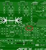
I started populating the first channel of my SR-200 amp. The PCB (v3.2) designed by Alexxmm has a cap of 18pF which is not on the schematic. The cap is connected between the collector of Q9 and the base of Q2. See attached picture for details. I have a few question in regards to this cap:
* What is the purpose of this cap?
* is it required?
Thank you.
Attachments
PSU-10
PSU-10 assembled and tested.
Since I only could attent 83 volts max with my lab power supplies I used that voltage as input of the PSU-10. According to the schematic it should be about 92 volts (65 volts AC). With 83 volts input I'm able to adjust the output between 68 volts and 81 volts. When lowering the input voltage, the adjustable range reduces too.
I will do some experimenting with resistor 2k2 (instead of 3k3) and 12 volt zener (instead of 20 volts) and 70 volts input. That should give me an adjustable range that includes about 60 volts output.
During testing I found out that there is an error in the Eagle library for the MPSA42 transistor. The device in the library has C and E pins reversed...
I attached a picture of the finished PCB. Note that the big caps are off the board.
Attachments
Good day, Mr. Mile! Tell me please nominal and maximal voltage PSU fo APEX SR100, what is its power per load of 8 ohms, and should I install Q7, Q8, Q9 on heatsink.
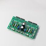
Diy file😀...
here is a version of the protect with film cap instead of the electrolytics.
speaker protection
sr 200
hi, to all,
i have built SR200 few months ago it worked well for several months but last week sound was distorted especially at low volume very distorted but at high volume it was tolerable sound is not that good but it was OK. the problem exist at low volume only and pre drivers on heatsink are very hot than before.
measured the output both DC 1-5mV only... AC 0.0V
Supply Voltage +/- 63V (psu10)
Speakers are also ok i tried on other amp.
please help,
thanks
regards
- Home
- Amplifiers
- Solid State
- Studio Reference Amplifier