You did not know that AC coupled negative feedback works?
Well, of course AC coupled feedback works, my comment about it was badly formulated. The background was that I have seen discussions where people make efforts to DC-couple the feedback paths (output anode to driver cathode, for example) to avoid potential problems caused by additional reactive components.
English isnt my first language and I often feel that less than half of want I meant to say actually ends up in my posts 😀
I guess it would work best on the bench with a purely resistive load on the output, yes.Nope, as the gain vs rotation is not constant on the the feedback.
There was a Russian American? poster who built custom single ended amplifiers.
He used negative feedback . . . But he also used Negative Resistance.
These were custom designed according to the loudspeaker system parameters.
His diyAudio handle started with the letter W.
Sounds like Wavebourn?
Those efforts, and your concerns, are worthwhile remembering. Adding an additional pole or zero to the feedback path must always be approached with great care, (I would say) especially at subsonic frequencies, where in an amplifier with OPT, whose primary (magnetizing) inductance moves about with signal level, moving a significant pole in (what's likely to be) the same region (a few Hertz or 1/10th of Hertz). Making predictability poor, and raising a concern.people make efforts to DC-couple the feedback paths (output anode to driver cathode, for example) to avoid potential problems caused by additional reactive components.
English isnt my first language and I often feel that less than half of want I meant to say actually ends up in my posts
Your English is better than mine, and seems perfectly clear to me. Do not fret.
All good fortune,
Chris
Yes, it is @Wavebourn by using nested feedback and positive current feedback IIRC:There was a Russian American? poster who built custom single ended amplifiers.
He used negative feedback . . . But he also used Negative Resistance.
This one? https://www.audiopax.com/e/pdfs/artigos/Valve-1997.pdfThen there was Eduardo B. DeLima from Brazil, who gave a presentation at one of the VSAC conferences in Silverdale, Washington State.
I don’t think to have the instruments to do so, nor knowing how to do it properly.Have you ever measured the amplitude, phase, and tone burst electrical signal responses at the junction of the amplifier output and loudspeaker input . . . I have.
May I ask you what can be learned from this test? You made me curious now!
I’ve done it on PP and only simulated in SE with what French call “Correction Différentielle”: you take the output signal you want to correct, scale down and subtract the input signal you want to reference it to.Switchable NFB can be easy if it's ordinary global NFB but it would become much more complicated in any topology where the feedback network affects the DC voltages.
What you get is the difference between the two, that is the distortion (only).
Then you can amplify this distortion-only signal as much as you need (within stability range) to target the needed Zout.
Amplifying only the distortion, it will not affect the sensitivity of the amp.
I fully understand your feelings, because I work with people all around the globe and I always say that you can easily understand my skills in communicating in a certain lenguage because my use of peryphrases is inversaly proportional to how much I master the language: in Italian is just for fun, in English is occasional, in French is sporadic, in Spanish is an intercalate 😃 (but I’m working on it!).English isnt my first language and I often feel that less than half of want I meant to say actually ends up in my posts 😀
In any case, your English seems fine to me, don’t worry!
Fuling,
Your English is good.
I merely made an assumption about what you said.
And now I realize what you were saying about using DC coupled negative feedback, and not complicating the circuit by using AC NFB.
Once, I made that tradeoff when I used a series RC for the negative feedback.
I started the amplifier with Schade negative feedback, but I wanted to change the negative feedback to the driver cathode.
Given the output stage's plate volts, my desired amount of negative feedback, and the driver's cathode self bias, it was easier for me to just put a capacitor in series with the NFB resistor that went from the output plate to the driver cathode resistors (no need to change the resistors, so I could keep the same bias on the driver tube. DC coupling would have required changing the driver cathode's resistor values.
I often go for simple changes to prove what a topology can do, or not do, for me.
But my simple solution of a cap in series with the NFB resistor had a disadvantage, the gain increased to open loop gain for frequencies below 20Hz.
Try a 3Hz record warp, or a 10Hz cartridge resonance, when the turntable is on a bouncing floor; those problems are not good for that amplifier.
Keep up the good work!
You (and others) are right . . . I was talking about Wavebourn.
zintolo,
Boy, I am having trouble keeping up to everybody's questions. (I enjoy, but get worn out).
Eduardo:
The Valve magazine you posted is part of what Eduardo wrote about, and gave in his presentation. So long ago, I can not remember much.
I was blessed to be at all the VSACs; I gave some presentations myself there, as well as dragging tube amplifiers for display, discussion, and to be used in my presentations, and two other presentations.
Measurements:
From about 1996 or 1997, until 2002, I had access to the worlds best Vector Network Analyzer (Rohde & Schwarz VNA) that could not only do RF work at GHz, but could go down to 10Hz, and had good dynamic range from that low frequency, to way above the highest audio frequencies.
I started measuring interstage transformers and output transformers; Inductance, leakage inductance, distributed capacitance, complex impedance, frequency response, and phase versus frequency.
And then I measured 2 stage triode amplifiers with DHT outputs; they did not have any negative feedback.
It was easy to measure the gain and phase versus frequency. I measured the amplifiers using an 8 Ohm non-inductive power resistor.
I was hooked on those measurements.
Then I got an idea . . . Why not measure the non-negative feedback amplifiers when they were connected to a real loudspeaker.
Soon, I was measuring the amplifier into an 8 Ohm load, then comparing it to the amplifier driving a loudspeaker.
Of course, I decided to measure the loudspeaker impedance and phase angle versus frequency by itself without the amplifier, and try to relate the loudspeaker measurements to the amplifier plus loudspeaker combination.
I must be sure that everyone understands, these were all electrical measurements.
The graphics were very good and very powerful, to teach about loudspeakers electrical characteristics, and output transformers characteristics by themselves, and as they were driven by various rp of various DHTs with an 8 Ohm load, and then with a loudspeaker load.
One factor that allowed me to measure loudspeakers, and amplifier loudspeaker combinations was the very wide dynamic range, and very low noise floor of the Rhode & Schwarz VNA.
I could use very low amplitudes to drive the loudspeakers, to keep the tweeters safe from burnout.
I did not use high power when I had the loudspeaker connected to the amplifier, so the measurements did not include the effects of woofers whose voice coils moved partway out of the magnetic pole pieces; nor did it include the effects when the woofer cone's outer suspension's excursion, and voice coil spider's excursion were at a point where Hooke's Law for springs was violated (beyond the maximum linear range of the suspension).
loudspeaker impedance changes at high electrical drive levels.
So that is another set of measurements that I never did.
There was No microphone, No anechoic chamber, And No acoustic measurements of any kind.
Last edited:
Ending the message there is like when in tv series you hear a scream and then the episode ends… we are more curious than before!There was No microphone, No anechoic chamber, And No acoustic measurements of any kind.
The measurements of loudspeakers Acoustic response is a completely different thing.
I think that doing microphone measurements requires some different equipment.
DHT amplifiers with no negative feedback have low to moderate damping factor.
Most loudspeakers that involve a good microphone and an anechoic chamber involve $$$, and are a completely different setup.
A high damping factor solid state amplifier is probably most often used to drive commercial loudspeakers.
I think that most driver curves are done with amplifiers that have high damping factors.
But there is a need for those kinds of measurements on amplifiers that do not have high damping factors,
and a need to make those measurements on loudspeakers that are designed to work best with tube amplifiers with low to moderate damping factors.
Otherwise how can a loudspeaker designer optimize his design?
If you need the rest of the story, someone else is going to have to do it.
I have not had any access to the Rohde & Schwarz VNA for decades.

In Audioreview in Italy there is one section of the large desk for test lab only dedicated to Loudspeaker.I think that most driver curves are done with amplifiers that have high damping factors.
With a AP Sy2 27xx + big ss amp to drive them and other stuff included B&K mic.
Another strong story.
Walter
It is simply, buy a Audio Precison stuff.I don’t think to have the instruments to do so, nor knowing how to do it properly.
Or a good sound card with Arta, can help in some test. Also Rew
Or this
https://quantasylum.com/products/qa403-audio-analyzer
Walter
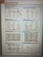
In post 11 a simple example of FB, 6 dBIt would be nice to be able to adjust the feedback ratio while the amp is running
In attach the results ( with a decent OT) , it ws built for headphone ( three different value, 10, 30 and 150 ohm) but also for a little efficent speaker
This is a response freq.
And Thd vs freq
Most of the published specs seen on speakers and their drivers are done with steady state sine waves where only one parameter is varied, usually the frequency. Sometimes you can find a compression curve where SPL vs amplitude is graphed. Do we listen to steady state single frequency information on our speakers?And, as long as you are developing the negative feedback versus the loudspeaker it will work with, I have to ask the question . . .
Have you ever measured the amplitude, phase, and tone burst electrical signal responses at the junction of the amplifier output and loudspeaker input . . . I have.
You will learn a lot if you do that.
Be careful, do not burn out any drivers.
Now ask yourself what is the instantaneous input impedance of a loudspeaker playing real music. It is not constant and varies with the program material and volume level. Some simple music played at a low level does not pose a threat to the amp, speaker or listener. Now consider a musical scenario where a single note from say a guitar is being heard and a huge transient from a drum or drum stick whack on the rim of the drum comes along that tries to instantaneously reverse the speaker cone's travel.
I spent over a year trying to measure this phenomenon and was quite convinced that the speaker's impedance could actually go negative at the moment that the transient arrives. The reason for this search was to get to the real question which is how does your amplifier react to this. A simple SE tube amp with no feedback behaves a lot different than an SS amp with a near zero output impedance.
Warning, this is a deep rabbit hole with many branches.......don't go there.
right butMost of the published specs seen on speakers and their drivers are done with steady state sine waves
Little OT
In Audioreview was developped a TND ( Total noise Distortion)
The link on magazine ( only in Italian, excuse)
https://www.audioreview.it/tecnica/total-noise-distortion.html
https://www.audioreview.it/tecnica/total-noise-distortion-seconda-parte.html
It say a lot of things about loudspeaker
Walter
Now ask yourself what is the instantaneous input impedance of a loudspeaker playing real music. It is not constant and varies with the program material and volume level. Some simple music played at a low level does not pose a threat to the amp, speaker or listener. Now consider a musical scenario where a single note from say a guitar is being heard and a huge transient from a drum or drum stick whack on the rim of the drum comes along that tries to instantaneously reverse the speaker cone's travel.
Someone on another forum once called SETs "a special interest for people with highly specialized speakers" or something like that. I think the quote above explains pretty well why. Most people seem to agree that SETs are at their best when they don't have to do any real work, ie playing soft music through hi-eff fullrangers in horns or pipes. Move the driver to a BR box, add 20-40 grams of moving mass and a passive crossover and watch the the demands on the amplifier change.
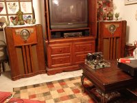
Back in the late 80's my audio flowed through silicon based life forms. I bought a pair of Yamaha NS-10M Studio monitors for my home recording efforts which I still have. The first Tubelab amp was a 45 based SET that evolved into the TSE and TSE-II. Granted 2 WPC will not rock the world through the Yamaha NS-10's but they didn't sound bad. As time passed I built a pair of DIY speakers by stuffing a pair of Hawthorne Silver Iris two way coaxial drivers into a matching pair of 1941 vintage Zenith console radios. Here 2 WPC was quite loud and the bass actually shook the (cheap sheetrock) walls.
By this time, I had developed the SSE, which is a SE amp that could run 6L6GC's, EL34's, 6550's, or KT88's in triode or UL. A pair of KT88's on 450 volts could make about 15 WPC. Connect that to the old radios and crank up some DSOTM ant you can hear the bass inside the house across the street!
I still prefer the sound of a single ended amp that makes 20+ WPC over most push pull amps. My current amp is UNSET based running a 26HU5 TV sweep tube. It makes the Yamaha's move around on the bench. None of these amps use any GNFB, but UNSET does apply local feedback around the output tube.
Attachments
- Home
- Amplifiers
- Tubes / Valves
- Strong local feedback + light global or the opposite?