I see no reason why it wouldn't work but I have not actually tried it. Since you are now feeding the feedback into the grid instead of the cathode a phase reversal will be needed. So one must reverse either the secondary or primary winding on the OPT. This will invoke a different set of stray capacitances than the usual connection. I usually only used CFB with low buck OPT like the $30 Edcor and the Hammond 125CSE, where the cathode feedback made a small but audible difference. A middle ear disease has taken most of my hearing, so I can't perform valid listening tests anymore.What if we reference the voltage divider of the UNSET to anode and secondary, instead of anode and ground? Can it be good to include the OPT dc coupled to the nfb this way?
@Tubelab_com
I have an Hammond 125ESE (that now is very expensive for what it is!) where I will try it with a EL34, 5k load on around 400V B+.
To sketch-up the idea, this is your UNSET amp with few modifications:

On LTSpice it gives 1 Wrms at 0,15% THD (20dB from 2nd to 3rd harmonic, 2nd harmonic with negative phase) and 16 Wrms at 1% THD (2nd and 3rd harmonics at same amplitude) with a Zout of 1.6 Ohm (considering 95 Ohm on primary and 0.2 Ohm on secondary).
Seems promising!
I have an Hammond 125ESE (that now is very expensive for what it is!) where I will try it with a EL34, 5k load on around 400V B+.
To sketch-up the idea, this is your UNSET amp with few modifications:
- Still cheap, but different tubes;
- Bootstrapped from low impedance pmos source-follower to the load of the driver make it see a CCS load;
- Increased local feedback of the output tube from 10 to 20% because of the behaviour of the GU50;
- Pmos source follower still stays below 10 W of dissipation;
- Local direct feedback dc coupled to the anode of the output tube and the secondary of the OPT instead of ground.
On LTSpice it gives 1 Wrms at 0,15% THD (20dB from 2nd to 3rd harmonic, 2nd harmonic with negative phase) and 16 Wrms at 1% THD (2nd and 3rd harmonics at same amplitude) with a Zout of 1.6 Ohm (considering 95 Ohm on primary and 0.2 Ohm on secondary).
Seems promising!
This UNSET concept seems to be an effective way to turn cheap sweep tubes into faux-DHTs in the 2A3/300B size range. With an extra Mosfet between the feedback divider and the grid, wouldn't this also be a way to turn cheap(ish) high mu transmitter triodes into 300B/845-like tubes?
I recently finished my 808 SE amp, a simple design with choke loaded cathode followers as grid drivers and CFB from the 16R tap to tame the output impedance. Definitely an FX box, but a nice sounding one. Next in the line is a smaller amp using Taylor T20/TZ20 triodes and it would be a bit boring to build the same thing again but with smaller components. UNSET is one of the things I would like to try, even if I must admit that I'm a bit reluctant to put "silicon fuses" (mosfets) in series with my fairly rare and expensive vintage triodes...
One way to avoid the mosfets (as a side note: I'm not worried about any sonic degradation from Mosfets, I just want to avoid any scenarios where they can fail and destroy the tubes and transformers) would be to use a transformer instead of the P-channel follower. Such circuits has been mentioned before on this forum and elsewhere but most of the literature and schematics on the web discusses RF circuits.
Probably a stupid idea, but I happen to own a pair of LL1671/50mA interstage transformers that can be wired as 1:1, 2:1 or 4:1. They should be suitable for some grounded grid experiments. And why stop here, why not put the OPT secondary in the cathode circuit too for some CFB? This topology could be named "the pillar of idiocracy"... 😀
The nice thing is that you can decide to have a more or less linear (with lower or higher rp) triode by changing the feedback ratio.This UNSET concept seems to be an effective way to turn cheap sweep tubes into faux-DHTs in the 2A3/300B size range.
At the same time, an higher feedback ratio will give you more linearity and more power, because the power dissipated by the pmosfet helps to get some more watts from the amp.
Yes, UNSET can be applied to anything, from triodes to pentodes to mosfets.With an extra Mosfet between the feedback divider and the grid, wouldn't this also be a way to turn cheap(ish) high mu transmitter triodes into 300B/845-like tubes?
You can also apply the UNSET (positive) feedback to the pmosfet and "pentodify" a triode while driving it from the grid as usual.
The UNSET concept works to make large TV sweep tubes into pseudo DHT's with nice triode curves. It can also be used to turn a high Mu triode into a low Mu triode. I didn't need any extra mosfet though, just two resistors. I was not using transmitter triodes though. I used a TV beam regulator triode like the 6HV5. I have not tried to pentodify a triode since I have far more 20 to 40 watt pentodes than triodes in my tube stash. I have however created a two stage ""UN" SET breadboard that makes 20 WPC through an OPT and has NO tubes, just 5 mosfets per channel. I have called it the FETSET. I have been tweaking as time permits but it sounds really good now and a PCB layout has been started.

The nice thing is that you can decide to have a more or less linear (with lower or higher rp) triode by changing the feedback ratio.
It would be nice to be able to adjust the feedback ratio while the amp is running. May not be easy though, switching between different resistors would change the bias and probably cause loud thumps in the speakers. A coupling cap between the feedback resistors and the grid would help but my gut feeling tells me we don' t want reactive components in the feedback path.
I didn't need any extra mosfet though, just two resistors. I was not using transmitter triodes though.
I guess any tube that requires positive grid bias, or draws grid current at any part of the cycle, would need a Mosfet buffer between the feedback divider and the grid?
Ale Moglia is on to something vaguely similar here with 811A and Schade feedback: https://www.bartola.co.uk/valves/tag/schade-feedback/
no, only on the output tube..@TonyTecson have you applied Schade nfb to the driver as well? It is a very simple yet effective kind of feedback, the drawback I see on the driver stage is the low input impedance of the amp.
can you share schematics? thanksThe UNSET concept works to make large TV sweep tubes into pseudo DHT's with nice triode curves. It can also be used to turn a high Mu triode into a low Mu triode. I didn't need any extra mosfet though, just two resistors. I was not using transmitter triodes though. I used a TV beam regulator triode like the 6HV5. I have not tried to pentodify a triode since I have far more 20 to 40 watt pentodes than triodes in my tube stash. I have however created a two stage ""UN" SET breadboard that makes 20 WPC through an OPT and has NO tubes, just 5 mosfets per channel. I have called it the FETSET. I have been tweaking as time permits but it sounds really good now and a PCB layout has been started.
https://www.diyaudio.com/community/threads/unset-beta-board-build.376124/can you share schematics? thanks
Fuling,
Do you want to compare different levels of negative feedback . . . on the fly?
You can build a simple switch box.
Build identical L and R channel amplifiers, Except for a Different amount of Negative Feedback on L Versus R.
Put 2 loudspeakers side-by-side, one from the L amp, and one from the R amp. Mono-Blocks or Stereo amplifiers both work for this test.
1. I have sent the L channel music signal from the signal source, then sent it to Both L and R channel amplifiers.
Then, I reversed one speakers connections (out of phase now); Faced the speakers to each other, about 1 inch away, and turned the volume down on the amplifier that has less negative feedback (thus has more gain). When the sound from the 2 speakers Null to silence, the gains are exactly equal.
Do not forget to reconnect the one speaker back to correct phase.
Now, pick your favorites of "listening test music", use only the L channel signal out.
Left channel music signal:
Apply that to a SPDT switch, with the music sent first to the L channel amp, then to the R channel amp, then alternate back and forth.
Same music going to each amp, one at a time, just different time portions of the music.
Repeat again, for different time portions.
Do not forget to reduce the volume control on the amplifier that has less negative feedback, it has more gain than the other amp.
This works great for me, all my power amplifiers have a volume control at the input, and I already did that in 1. above.
Right channel music signal source:
Change the signal source to its Right channel, and run the test with the the right channel music going to the SPDT switch.
Conduct the test again, just as above, except this time with the music instruments that are in the Right channel.
Repeat again, for different time portions of the music.
Do not forget to reduce the volume control on the amplifier that has less negative feedback, it has more gain than the other amp.
This works great for me, all my power amplifiers have a volume control at the input, and I already did that in 1. above.
This takes a fair amount of work to set up, but it is tried and true.
It works!
Testing in stereo this way is just too much work.
It would requires 2 stereo amplifiers, with different negative feedback ratios (4 amp channels, 2 with one level of negative feedback, and 2 with a different level of negative feedback.
Then you need 4 speakers side by side, L1, L2, and R1, R2; so you can adjust the gains for Nulls of sound.
And, you would also need a DPDT switch.
Making good amplifier tests on the test bench is difficult.
Making good listening tests is much more difficult.
Do the work, get results; or never be sure.
Have Fun!
Last edited:
Thanks 6A3sUMMER for a very elaborate reply!Do you want to compare different levels of negative feedback . . . on the fly?
Yes and no. To be more specific, the idea is to be able to tune the output impedance to match the speakers currently in use. I have two pairs of speakers (and counting...) in my hobby room, one pair of front horn/BR hybrids loaded with low Qts 18Sound drivers and a pair of plain BR boxes with medium Qts Eminence drivers. The Eminence cabs sound better matched with low Zout amps, while the horns usually sound fuller and richer connected to low NFB amps.
Switchable NFB can be easy if it's ordinary global NFB but it would become much more complicated in any topology where the feedback network affects the DC voltages.
Here is the "simplified schematic" of the two stage amp board. It is the schematic of the useful stuff without all of the confusing jumpers needed to accommodate lots of different tubes. It has a stereo pair of two stage amps and a simple 5AR4 based power supply. The 5AR4 can not support a pair of 25+ watt channels, so fast recovery diodes must be used for a single board amp.
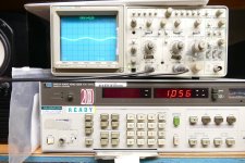
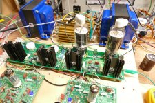
Need LOTS of power. I laid out a board with a pair of UNSET output stages, no driver, no power supply. One board can be used for an SE stereo output pair with external drivers and a suitable power supply. The fat TV sweep tubes that I like make 20 to 25 watts in SE depending on how far you bend the specs. Where these things ROCK is in push pull. I used two of the UNSET octal output boards, each with their stages wired in parallel. I then drove them with one of my Universal Driver Boards and fed it with an adjustable power supply capable of up to 650 volts at 1.7 amps. I set it at 625 volts, current knob up full.
I got the MOAT (mother of all transformers) off the shelf for OPT duty. With about 5 minutes of knob twisting, I was touching the point of clipping at 525 watts with 3.8% THD. Dialing the drive back to a mere 350 watts results in 0.82% THD. Current consumed on the 625 volt supply was about 1.25 amps. My current DUMM BLONDE idea is to wire 13 of these cheap 48 volt supplies in series. You need to remove the cap from the negative output to safety ground before trying this! I have not tried 13 in series yet, but 5 in series have successfully fed a solid state FETSET SE board 240 volts at 250 mA.
https://www.mpja.com/48-Volt-Power-Supply-3A-Cosel-LDA150W-48/productinfo/34713+PS/
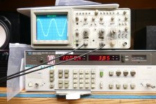
A stereo amp was tested with one UD board feeding each UNSET octal output board with some Edcor 3300 ohm 100 watt OPT's. Cranking the drive to get 200 watts out gets 3.85% THD. Dialing it back to 100 watts gets 1.08% THD with 0.74% at 10 watts, and 0.416% at 1 watt. No negative feedback was used other than the UNSET configuration in the output stage. The driver tubes are 6FQ7's with one LTP driving a second LTP. Output tubes are 26HU5's. 6LW6's will make a bit more power, but 525 watts are way overkill for me, and I have more 26HU5's than any 'LW6s.
Need LOTS of power. I laid out a board with a pair of UNSET output stages, no driver, no power supply. One board can be used for an SE stereo output pair with external drivers and a suitable power supply. The fat TV sweep tubes that I like make 20 to 25 watts in SE depending on how far you bend the specs. Where these things ROCK is in push pull. I used two of the UNSET octal output boards, each with their stages wired in parallel. I then drove them with one of my Universal Driver Boards and fed it with an adjustable power supply capable of up to 650 volts at 1.7 amps. I set it at 625 volts, current knob up full.
I got the MOAT (mother of all transformers) off the shelf for OPT duty. With about 5 minutes of knob twisting, I was touching the point of clipping at 525 watts with 3.8% THD. Dialing the drive back to a mere 350 watts results in 0.82% THD. Current consumed on the 625 volt supply was about 1.25 amps. My current DUMM BLONDE idea is to wire 13 of these cheap 48 volt supplies in series. You need to remove the cap from the negative output to safety ground before trying this! I have not tried 13 in series yet, but 5 in series have successfully fed a solid state FETSET SE board 240 volts at 250 mA.
https://www.mpja.com/48-Volt-Power-Supply-3A-Cosel-LDA150W-48/productinfo/34713+PS/
A stereo amp was tested with one UD board feeding each UNSET octal output board with some Edcor 3300 ohm 100 watt OPT's. Cranking the drive to get 200 watts out gets 3.85% THD. Dialing it back to 100 watts gets 1.08% THD with 0.74% at 10 watts, and 0.416% at 1 watt. No negative feedback was used other than the UNSET configuration in the output stage. The driver tubes are 6FQ7's with one LTP driving a second LTP. Output tubes are 26HU5's. 6LW6's will make a bit more power, but 525 watts are way overkill for me, and I have more 26HU5's than any 'LW6s.
Attachments
-
 P4000794.JPG418.4 KB · Views: 50
 -
 P4000789.JPG327.1 KB · Views: 51
 -
 P4000788.JPG325.1 KB · Views: 53
 -
 P4000787.JPG518.9 KB · Views: 58
 -
 P4000809.JPG327.8 KB · Views: 51
 -
 P4000808.JPG315.4 KB · Views: 45
 -
 P4000813.JPG442.2 KB · Views: 42
 -
 P4000811.JPG364.1 KB · Views: 49
 -
 P4000812.JPG333.8 KB · Views: 46
 -
Unset_Simplified_Schematic.pdf117.9 KB · Views: 81
-
 P4000795.JPG423.7 KB · Views: 44
You can keep the dc reference and tailoring ac by decoupling a parallel pot to ground.It would be nice to be able to adjust the feedback ratio while the amp is running.
Yes, you can control the AC feedback level without affecting the DC voltage by putting a pot in series with a decent quality cap and connecting it from the tube's control grid to ground. As the feedback level changes the amps gain changes, so one needs to have one hand on the volume knob and the other on the feedback knob.
Good to hear that AC coupled feedback works, that simplifies things a lot.
Perhaps one could custom build a four-gang stepped attenuator where two decks sets the feedback and the remaining two adjusts the input level to keep the gain constant?As the feedback level changes the amps gain changes, so one needs to have one hand on the volume knob and the other on the feedback knob.
Fuling,
You did not know that AC coupled negative feedback works?
1. Passing AC but not passing DC:
How about Schade negative feedback, that often only couples through a capacitor?
And . . .
As far as I know, all global negative feedback that comes from a transformer's secondary is AC negative feedback.
Those output transformers are very poor at passing DC from the primary to the secondary.
If they do, it is a short, fix or toss out the transformer.
2. Passing DC but not passing AC:
There is a device that passes DC on to the next filter "stage", but rejects common mode AC from passing on to the next filter "stage" . . .
That is called a Common Mode Choke.
. . . Magnetic devices that only pass DC.
Last edited:
Fuling,
HP made great 50 Ohm step attenuators, 1 dB and 10 dB steps.
With 2 sets of each, it was very easy to test for the 1 dB compression point of amplifiers (not just RF, but Audio too).
US Navy (standard) "Test Methods and Practices"
Right Full Rudder! . . . Hang on Tight to something solidly attached to the deck or bulkhead.
It is no fun to be high-lined underway from a destroyer to a carrier or oiler, and then re-delivered to a hospital.
And I used those HP attenuators on many other electronic jobs too.
Last edited:
Nope, as the gain vs rotation is not constant on the the feedback.Perhaps one could custom build a four-gang stepped attenuator where two decks sets the feedback and the remaining two adjusts the input level to keep the gain constant?
zintolo,
Stepped attenuators of a particular step size versus the other feedback resistances will work OK.
But you have to re-calculate different step sizes, each time a new amplifier topology and circuit comes along.
And the input signal attenuator has to match the feedback effective attenuation.
Too much work for most people.
4 gang potentiometers, forget it.
Hope Springs Eternal . . .
There is more than one way to control different speaker systems.
My bad memory is back.
There was a Russian American? poster who built custom single ended amplifiers.
He used negative feedback . . . But he also used Negative Resistance.
These were custom designed according to the loudspeaker system parameters.
His diyAudio handle started with the letter W.
Then there was Eduardo B. DeLima from Brazil, who gave a presentation at one of the VSAC conferences in Silverdale, Washington State.
He related the single ended output transformer's inductance, the woofers inductive reactance, resistive, and capacitive reactance below resonance, at resonance, and above resonance respectively.
And, as long as you are developing the negative feedback versus the loudspeaker it will work with, I have to ask the question . . .
Have you ever measured the amplitude, phase, and tone burst electrical signal responses at the junction of the amplifier output and loudspeaker input . . . I have.
You will learn a lot if you do that.
Be careful, do not burn out any drivers.
Have Fun!
Last edited:
- Home
- Amplifiers
- Tubes / Valves
- Strong local feedback + light global or the opposite?