Good point indeed. Was it a double-phase rectifier?
Jan
One separate phase per bridge I believe using two separate isolated windings.
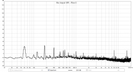
Virtually all transformers are designed to just run into saturation. It improves their regulation. The particular transformer is a cheap design and rated for 115 volts and is being used above that. Attached is what transformer saturation looks like using the cleanest transformer in my tests. It has a 220 volt primary and is fed from an amplifier producing less than .05% distortion. All odd order harmonics. The rectifiers would cause even order harmonics.
The second plot is a more typical transformer. compare that to the first post's plot.
Thanks for the plots - it does look very familiar. Umm... how does one check to see if a transformer is saturated? I must have missed that.
How about #40.....
I did not realize that this was the proposal on how to check for saturation. Is this what you mean?
If you use a buck transformer to reduce the mains voltage it will not significantly lower the rail voltage.
I don't have a 400VA buck transformer, or any buck (voltage reduction) transformer. I assume this means just a slight reduction as in maybe use a Variac? Don't have one of those either. Is there another way? I have a clamp on current probe and 3 DMM's.
The transformer makes a slightly audible hum, even at 2.5amps. Would that be an indication of saturation?
Antek makes rather nice transformers in my experience - at least physically well-built and rahter large and heavy substantial feeling. Would Avel-Lindberg be a higher quality brand? They cost more. This particular model was about $53 so not particularly "cheap" in my book.
https://www.plitron.com/news/enhanced-toroidal-technologies/
Any body have idea what is this "LoSTRAY" technology? What can be that?
Any body have idea what is this "LoSTRAY" technology? What can be that?
You only need a 12 volt 4 amp transformer to buck the voltage. Put the twelve volt winding in series with the primary. Line in goes across the whole thing line out across the primary. Check the voltage with a light bulb in series first. 25 watts should do. If it lights up switch the secondary leads.
Noise is a sign of saturation.
Noise is a sign of saturation.
Nothing Wrong with the Anteks per se.
Certainly that one... for driving a Pass circuit.
Typically they are DEAD silent .. achieved by simply following the DIY PS circuit.. Exactly.
Couldn't be a simpler solution 😉
Certainly that one... for driving a Pass circuit.
Typically they are DEAD silent .. achieved by simply following the DIY PS circuit.. Exactly.
Couldn't be a simpler solution 😉
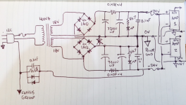
I fixed the circuit according to this schematic, which now has a star ground from the clean-side of the CRC 0v terminal. The ground from there goes to a GLB consisting of an 8R resistor paralleled with 0.1uF film cap and two large 8A back-to-back diodes which then connect to earth ground and chassis ground. I verified that the PCB's are not connected to the chassis ground via the standoffs. The setup seems to have lower noise, but I can still hear some hum. The amp outputs measure 0.6mV AC with my Fluke 101. Maybe this is normal for a Pass M2?
Schematic:
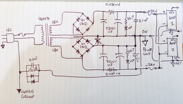
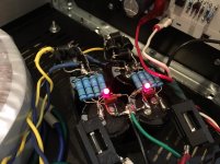
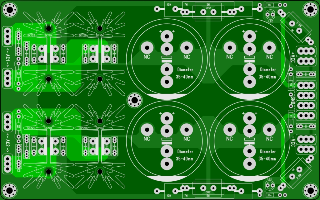
Closeup of CRC showing *2* full wave bridges with 8 diodes:

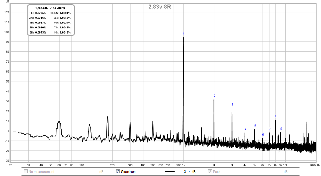
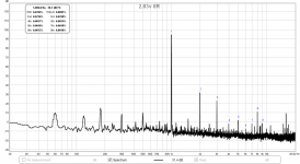
Measurements of FFT at 2.83v into 8R (THD is about 0.07% which is pretty good for such a simple zero feedback amp capable of 25w output):
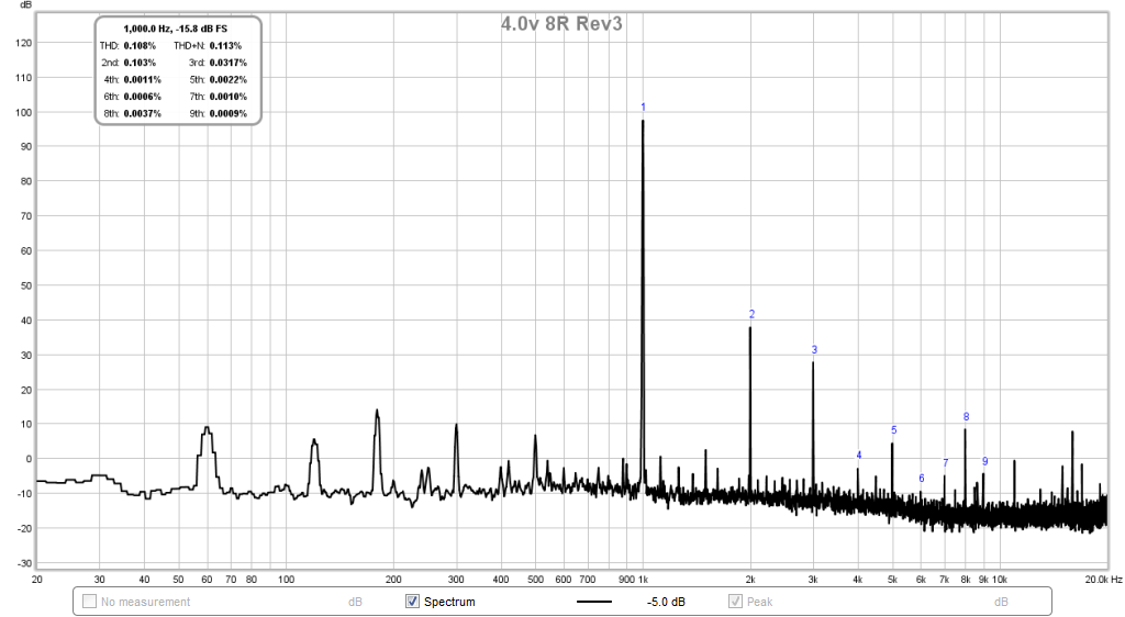
4v into 8R:
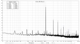
8v into 8R:

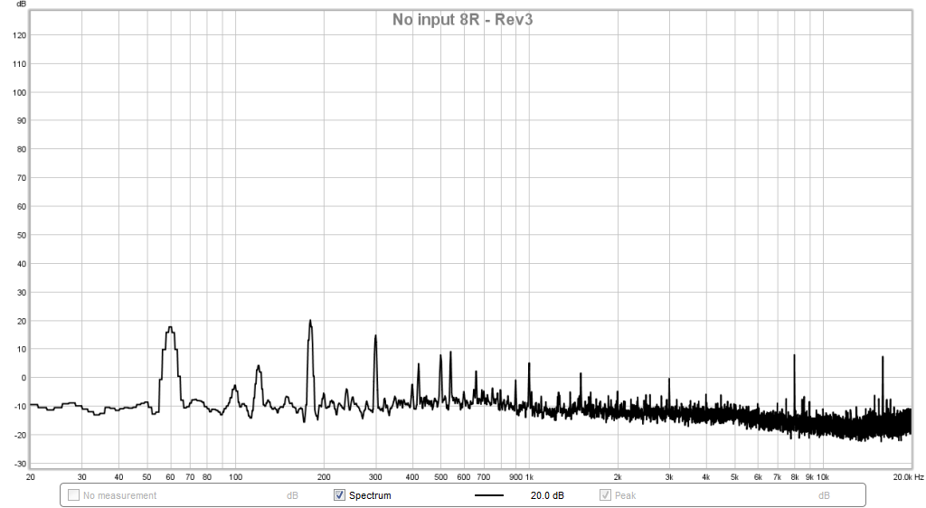
0v (no signal):
It still is not as quiet as the SMPS bricks. I think it is better though - listening to it now. The hum is onlu audible if I put my ear right next to speaker cone.
Schematic:
Closeup of CRC showing *2* full wave bridges with 8 diodes:
Measurements of FFT at 2.83v into 8R (THD is about 0.07% which is pretty good for such a simple zero feedback amp capable of 25w output):
4v into 8R:
8v into 8R:
0v (no signal):
It still is not as quiet as the SMPS bricks. I think it is better though - listening to it now. The hum is onlu audible if I put my ear right next to speaker cone.
Attachments

You seem happier with the latest result 🙂
Even though you have drawn the PSU, the reality is that the real design could be different. Even soldering a bunch of wires together and saying 'that point is ground' can have issues due to differing current flows within the joint, and so the differing take off points being slightly different in potential.
Even though you have drawn the PSU, the reality is that the real design could be different. Even soldering a bunch of wires together and saying 'that point is ground' can have issues due to differing current flows within the joint, and so the differing take off points being slightly different in potential.
It appears from post # 89 that the culprit was indeed, as I expected, wiring and ground reference rather than xformer saturation.
But for future reference: if you sustect xformer saturation, temporarily replace it with an overrated one specified for your actual mains voltage.
Jan
But for future reference: if you sustect xformer saturation, temporarily replace it with an overrated one specified for your actual mains voltage.
Jan
You seem happier with the latest result 🙂
Even though you have drawn the PSU, the reality is that the real design could be different. Even soldering a bunch of wires together and saying 'that point is ground' can have issues due to differing current flows within the joint, and so the differing take off points being slightly different in potential.
I have a couple of these Project 16/Prasi CRC boards that I will try next. I even got some MUr880 diodes to go with it. Let's see if things improve. I know that my grounding scheme is a lot better now.
yes, unfortunantly just a bigger VA rated Xfmr won't help much - it has to wound for the higher line Vif you sustect xformer saturation, temporarily replace it with an overrated one specified for your actual mains voltage.
There is a drawing error on my schematic. The lower bridge shows negative rail connected to AC in. Actually connected to negative of bridge.
If you haven't seen this there is a very clear diagram showing how to physically lay out the star grounding point, or "T" as it is in reality shown here http://hifisonix.com/wordpress/wp-c.../How-to-wire-up-a-Power-Amplifier_Updated.pdf
I have a couple of these Project 16/Prasi CRC boards that I will try next. I even got some MUr880 diodes to go with it. Let's see if things improve. I know that my grounding scheme is a lot better now.
I find it can help to think of the problem as a DC one.
The amplifier, its input and its output and its feedback return points should all be such that the amplifier is unaffected by the wiring to and from the PSU.
For example...
If the amp is set to give 10 volts DC at the output and you then connect a 10 ohm load then 1 amp should flow. The output voltage of the amp should be constant and should not fall (although an amp with high output impedance would show a small drop) and certainly it should not rise (which can happen in poor wiring schemes as the feedback return or input ground is raised or lowered in potential by current flow in the wiring).
The other channel should show no rise or fall in its output voltage as you connect and disconnect the load. That should be so with the left and right inputs connected together at a common low impedance point (such as will occur when coupled to a preamp).
Think of it as a DC problem and much of it will start to make more sense.
There are still a few more things you could try first.
1. Move the PSU to the middle of the chassis.
2. Use very short thick leads connecting the grounds. The goal here is to lower the resistance/inductance between the amp boards.
3. Add a 100nF capacitor between the input ground and chassis of each amp board.
1. Move the PSU to the middle of the chassis.
2. Use very short thick leads connecting the grounds. The goal here is to lower the resistance/inductance between the amp boards.
3. Add a 100nF capacitor between the input ground and chassis of each amp board.
2. Use very short thick leads connecting the grounds. The goal here is to lower the resistance/inductance between the amp boards.
.
I would say impedance not inductance, inductance is determined by the lead positions. This is where bus routing (double sided broadside coupled routing or twisted pair cables helps reduce inductance.
I have a couple of these Project 16/Prasi CRC boards that I will try next. I even got some MUr880 diodes to go with it. Let's see if things improve. I know that my grounding scheme is a lot better now.
As important is where you ground your signal connections, and your measurement connections.
The supply grounding scheme is one thing, but it won't solve it if you pick off the signal references at the wrong point.
Supply grounding is not aimed at avoiding noise/hum to appear across a piece of wire - it can't; wire is impedance, and there is always wire between xformer, rectifier, capacitor, load; and current through it always generates noise/hum. The object is to avoid that happening on a piece of wire that also is a reference for the signal. So there's two parts of it.
It might help to draw that part of the system as well.
Jan
I'm glad he finally got there, although 9 pages to correct a simple (and all too common) grounding error seems a lot.
Try adding snubbers across the transformer secondaries. Ringing in the charging pulse loop will be at a much higher frequency then mains AC and so will more easily get into the audio circuit, but then end up as buzz due to bandwidth limiting.
Try adding snubbers across the transformer secondaries. Ringing in the charging pulse loop will be at a much higher frequency then mains AC and so will more easily get into the audio circuit, but then end up as buzz due to bandwidth limiting.
- Status
- Not open for further replies.
- Home
- Amplifiers
- Power Supplies
- Strange Forest of Noise with Linear PSU